Knowledge · Measuring
How to measure pipe flanges, pipes and fittings correctly
What you have to measure depends on the component – for a pipe it is outside diameter and wall thickness, for a pipe flange bolt circle, outside diameter and number of holes, for an elbow angle and centre-to-end dimension. And it depends on where you measure: the standard defines a measuring point for every dimension, and whoever measures elsewhere later compares the wrong value with the table. Choose your component above. For each component you will find the key measuring picture, the core rule and the typical error – and below that the measuring tools with formulas, also for the site without calipers.
- Components
- Pipe · Pipe flange · Elbow and fitting · Dished end and cap · Gasket · Welding end
- Measuring points to
- EN 10216-2, EN 1092-1, EN 10253-2, DIN 28011, EN 1514-1, ASME B16.5 and B16.25
- Measuring tools
- Calipers, circumference tape, folding rule or tape measure, string, protractor
- Next
- Dimensional drawing of your size with tolerances on the component page · Identify a pipe flange from measurements
What is in front of you?
Whether you call it measuring pipe diameter, measuring a pipe flange, finding the pipe flange size, measuring wall thickness or determining the bolt circle – every component has its own measuring points. Jump to your component:
Measuring a pipe: outside diameter and wall thickness
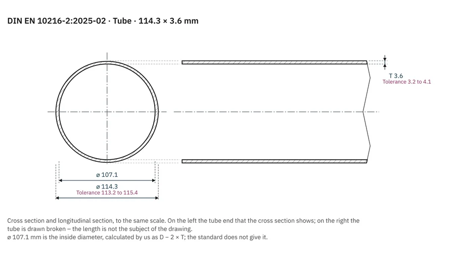
Core rule: The outside diameter D is measured across the edge, the wall thickness T at the pipe end as the full wall – from the outer surface to the inner surface, at the end face. The standard (EN 10216-2, clause 11.9) checks the wall thickness at both pipe ends; that is where the tolerances of the table apply.
How to do it: Place the calipers with both jaws squarely across the pipe, turn the pipe and measure in two directions – the mean is D, the difference shows the out-of-roundness. For the wall thickness, take the open end with the jaws or the depth gauge from outside to inside. If you only have the inside diameter, T = (D − inside diameter) ÷ 2; conversely the inside diameter is D − 2T. On large pipes use a circumference tape: it shows the diameter directly or gives the circumference U, then D = U ÷ π (example: circumference 359 mm ÷ 3.1416 = 114.3 mm, i.e. the DN 100 pipe).
Typical error: Taking the nominal size as a dimension. “DN 100” is not a diameter and neither is “1 inch” – a 1 inch threaded pipe measures 33.7 mm outside, a 3/4 inch pipe 26.9 mm. The outside diameter is the dimension the trade lists and the standard tolerances; the wall thickness comes with it, and only both together name the size (DN is not a diameter, Measure the outside diameter, do not guess the nominal size). Second error: measuring the wall with the calipers across a bevel or a burr – then it comes out too thin or too thick.
All measuring pictures and tolerances for your size: Seamless tubes EN 10216-2 · Welded tubes EN 10217-1 · all pipe standards – the dimensional drawing of your size opens with the tolerance display switched on.
Measuring a pipe flange: bolt circle, outside diameter, holes and flange thickness
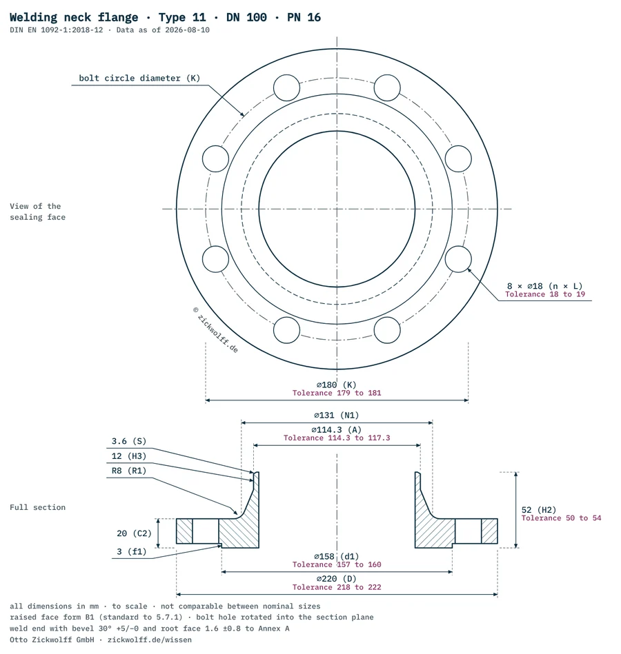
Core rule: Four values define a pipe flange – bolt circle K, outside diameter D, number of holes n with hole diameter L, and the flange thickness. The bolt circle is the circle through the hole centres. With an even number of holes, measure it from the outer edge of one hole to the inner edge of the opposite hole: the half hole here cancels the half hole there, and you have exactly the centre-to-centre dimension.
Without an opposite hole: With an odd number of holes or when the pipe flange is installed, measure the distance a between two adjacent holes (again outer edge to inner edge) and calculate K = a ÷ sin(180° ÷ n). Example DN 100 PN 16: eight holes, hole spacing 68.9 mm – 180° ÷ 8 = 22.5°, sin 22.5° = 0.3827, so K = 68.9 ÷ 0.3827 = 180 mm. Plus D 220 mm, holes 18 mm for M16 bolts – the hole is always larger than the bolt.
Flange thickness: To EN 1092-1 you measure from the sealing face to the back of the plate, not at the hub – a raised face is already included in this dimension. To ASME B16.5 it is the other way round: the flange thickness tf applies without the raised face (1.5 mm – 1/16 inch – for Class 150 and 300, 6.4 mm – 1/4 inch – from Class 400); older tables before 2003 still included it for Class 150/300. Whoever compares here without looking at the standard is off by the height of the raised face.
Typical error: Measuring the bolt circle across the outer edges of both holes (one hole diameter too much) or estimating the outside diameter and then guessing the PN rating. With K, D, n and L our tool determines size and pressure rating – the question “Class 150 or 300?” is also answered by number of holes, bolt circle and outside diameter, not by eye: Identify a pipe flange from measurements.
All measuring pictures and tolerances for your size: Weld neck flange type 11 · Plate flange type 01 · Blind flange type 05 · Weld neck flange ASME B16.5 · all pipe flange types.
Measuring an elbow or fitting: angle, centre-to-end and radius

Core rule: Outside diameter and wall thickness are measured at the welding ends, never at the back of the elbow or on the body of the fitting – there the wall may be thinner than at the end according to EN 10253-2. A try square shows the angle: put one leg of the elbow against it, then the second leg shows the angle (90°, 45°, 180°). For a 90° elbow also measure W: elbow flat on the table, from the end face of one leg to the outside of the other.
Radius: The bend radius R is the radius of the pipe axis – it cannot be measured directly on the part. You calculate it from W: R = W − D ÷ 2. Example 3D elbow for the 114.3 mm pipe: W = 209 mm, so R = 209 − 57.15 ≈ 152 mm – the table value to EN 10253-2. The type gives the radius only roughly: 3D means about 1.5 × the nominal size (DN 100: 152 mm), not 1.5 × the outside diameter – the exact value is in the dimension table. For a 45° elbow the dimension is called Z, for a 180° return there is the dimension B from the openings to the crown and the centre-to-centre C = 2R. Tees and reducers are measured the same way: D and T per end, the dimensions F and G or L across the end faces.
Typical error: Measuring the wall at the back of the elbow and taking the part for undersize – or taking the radius on the outside. The outside has the radius R plus half the diameter, the inside R minus half the diameter. Rule of thumb: Measure the full wall – not the root face.
All measuring pictures and tolerances for your size: Elbows, steel · Elbows, stainless steel · Tees · Reducers · Elbow basics.
Measuring a dished end or cap: diameter, wall thickness and height
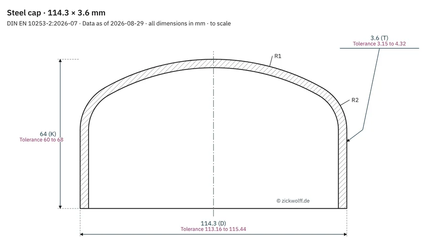
Core rule: The outside diameter is measured at the welding end across the edge, the wall thickness there as well – on the domed part the wall may be thinner because it is stretched during forming. The overall height runs from the edge of the welding end to the crown. For a dished end to DIN 28011 there is also the straight flange height: the cylindrical rim where the weld is made.
How to do it: Stand the dished end opening down on a flat surface, overall height with depth gauge or rule from the table to the crown; straight flange height from the edge to the start of the knuckle (where the wall leaves the vertical). Outside diameter with calipers or circumference tape at the straight flange, in two directions.
Typical error: Measuring the wall thickness in the middle of the dome and rejecting the part – the standard refers the nominal wall thickness to the welding end. Second error: confusing cap and dished end. The cap to EN 10253 has no cylindrical straight flange like the dished end; its height dimension is the overall height K from the edge of the welding end to the crown.
All measuring pictures and tolerances for your size: Caps, steel · Caps, stainless steel · Dished ends and caps – basics.
Measuring a gasket: inside and outside diameter, thickness
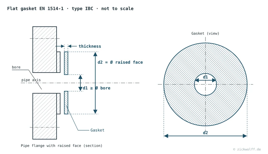
Core rule: A gasket is not measured on its own but assigned to the pipe flange: DN, PN and the facing of the pipe flange determine inside and outside diameter to EN 1514-1. With raised-face flanges (form B) the gasket sits inside the bolts and its outside diameter equals the raised-face diameter; with flat faces (form A) it can extend to the outside diameter of the pipe flange and then has bolt holes. Measure the thickness (usually 1.5 to 3 mm) with calipers at the rim, not at a compressed spot.
How to do it: Measure inside and outside diameter in two directions, for gaskets with holes also number of holes and bolt circle as for the pipe flange. If you have the pipe flange but not the gasket: raised-face diameter and bore of the pipe flange give the outside and the smallest sensible inside diameter – the gasket must not protrude into the bore.
Typical error: Measuring a used gasket and ordering those dimensions – it is compressed, swollen or torn. Better to measure the pipe flange and choose the gasket by DN, PN and facing (Rule of thumb: Seal before system).
Dimension tables: Flat gaskets EN 1514-1 · Flat gaskets DIN 2690 · all gaskets.
Measuring a welding end: end face, full wall – not the root face
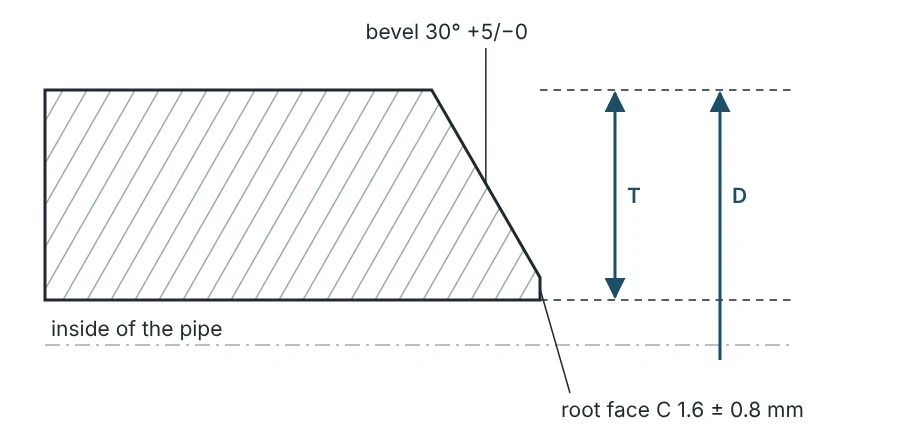
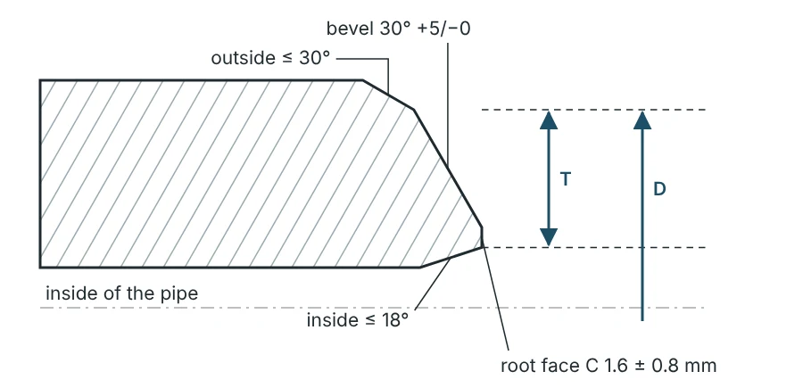

Core rule: Pipe, fitting and weld neck flange share the same measuring point at the welding end: the end face. The outside diameter D is taken on the extended outer surface, the wall thickness T as the full wall from the outer surface to the inner surface. The bevel (30° to EN, 37.5° to ASME B16.25) takes nothing from the wall, and the root face C of 1.6 mm is never the wall – it is only what remains after the bevel.
Special case weld neck flange: If the hub has an internal taper bore (EN 1092-1 figure A.3, 15°), the dimension at the end face is Sp – it corresponds to the pipe wall; the hub thickness S lies only behind the taper. On machined fitting ends (outside up to 30°, inside up to 18°) T runs from bevel edge to bevel edge, always the full wall.
Typical error: Taking the root face with the calipers and noting 1.6 mm “wall thickness” – or measuring behind the bevel, where the wall of a fitting may already be thinner. Rule of thumb: Measure the full wall – not the root face.
The box “Where to measure” with both drawing details is on every dimension page with a welding end: Pipes · Elbows · Weld neck flange type 11 · Welding ends to ASME B16.25.
Measuring tools: what with what – with formulas and error limits
To identify the size a folding rule is often enough; to compare with the tolerances of the standard you need calipers. The overview says what each tool can do and where its typical error lies.
| Measuring tools | What for | Accuracy | Typical error |
|---|---|---|---|
| Calipers (vernier calipers) | Outside diameter up to about 300 mm, wall thickness at the end, hole diameter, hole spacing, flange thickness | 0.1 mm (vernier) to 0.05 mm | Jaws placed at an angle or across the bevel; wall thickness measured across a burr |
| Circumference tape | Outside diameter of large pipes, elbows, dished ends; add out-of-roundness from two caliper directions | about 0.1 mm with the tape lying flat | Tape laid at an angle or across a weld seam – it measures the mean diameter, not the smallest |
| Folding rule or tape measure | Outside diameter across the edge, centre-to-end dimensions, heights, bolt circle across two holes | about ±1 mm | Not measured through the centre (chord instead of diameter); sufficient to identify the size from the table, not for tolerances |
| String or paper strip | Circumference of a pipe without calipers – circumference ÷ π | about ±1 to 2 mm in diameter | String stretches, strip lies at an angle; mark imprecise |
| Protractor or try square | Elbow angle, squareness of the end face, position of the sealing face | 0.5° to 1° | Placed on the bent part instead of on the legs |
| Depth gauge or rule | Height of dished ends and caps, straight flange height, depth of an internal taper bore | 0.1 mm (depth gauge), 0.5 mm (rule) | Placed next to the crown instead of on it |
The three formulas you need
Diameter from the circumference: D = U ÷ π. Put a string around the pipe, measure the circumference, divide by 3.1416. Example: 359 mm ÷ 3.1416 = 114.3 mm – the DN 100 pipe. And 171 mm circumference ÷ 3.1416 = 54.4 mm, so not a standard steel pipe: 54 mm is a press-fit pipe size, the DN 50 steel pipe would be 60.3 mm – the formula also exposes foreign sizes (Third-party pipe only by dimension table).
Bolt circle across two adjacent holes: K = a ÷ sin(180° ÷ n), a = distance between hole centres (outer edge to inner edge), n = number of holes. Example: a = 68.9 mm, n = 8 → K = 68.9 ÷ 0.3827 = 180 mm (DN 100 PN 16). For four holes the divisor is 0.7071, for twelve 0.2588.
Wall thickness from two diameters: T = (D − d) ÷ 2, d = inside diameter at the end. Example: (114.3 − 107.1) ÷ 2 = 3.6 mm. Conversely the clear bore: d = D − 2T.
Frequently asked questions about measuring
How do I measure a pipe, a pipe flange or an elbow correctly?
Per component at the measuring point the standard defines: pipe outside diameter across the edge and wall thickness at the pipe end, pipe flange bolt circle across two opposite holes, elbow D and T at the welding end - the page shows measuring picture, core rule and typical error per component, plus the formulas for measuring without calipers.
How do I measure a pipe flange?
Four values: bolt circle K from hole centre to opposite hole centre (measured outer edge to inner edge), outside diameter D across the edge, number of holes n with hole diameter L, and the flange thickness from the sealing face to the back. With these values the flange identifier determines size and pressure rating. With an odd number of holes, calculate the bolt circle from two adjacent holes: K = a ÷ sin(180° ÷ n).
How do I measure a pipe?
Outside diameter D with calipers across the edge, in two directions; wall thickness T at the pipe end as the full wall from outside to inside. The nominal size DN or the inch designation is not a measured value – what counts are outside diameter and wall thickness, and with both you find the size in the dimension table.
How can I measure the wall thickness?
At the open pipe end with calipers or depth gauge from the outer surface to the inner surface – at the end face, not across bevel or root face. Without access to the end, calculate from outside and inside diameter: T = (D − d) ÷ 2. The wall thickness of installed pipework is measured by ultrasound; that is an inspection task, not a size identification.
Measuring pipe diameter without calipers – is that possible?
Yes, via the circumference: put a string or paper strip around the pipe, measure the circumference and divide by π (D = U ÷ 3.1416). Example: 359 mm circumference is 114.3 mm outside diameter, the DN 100 pipe. Accuracy about ±1 to 2 mm – enough to find the size in the table, not to check tolerances.
What diameter does a DN 80 pipe flange have?
That depends on the pressure rating: a DN 80 pipe flange to EN 1092-1 has at PN 6 an outside diameter of 190 mm with bolt circle 150 mm and four holes 18 mm; at PN 10 to PN 40 it is 200 mm outside diameter, bolt circle 160 mm and eight holes 18 mm for M16 – the four pressure ratings share the same bolt pattern here but differ in flange thickness and height. All values per size and pressure rating with drawing: Dimensional drawing DN 80 PN 16 and Dimension table PN 6 to PN 40.
Your inquiry to Zickwolff
Send us what you have – designation, standard, quantity, date. We will clarify the rest with you.
One item or a question
Send inquiry
Not in stock? We procure it – single items too.
Designation, standard and quantity are enough.
Several items
Send bill of materials
200 items? One parts list is enough – we deliver complete.
Attach it as a file.
Helpful if already known: project and country, date needed, certificates, packaging and language of the packing lists. If anything is missing, we will ask.
It is urgent
Request express
When do you need it? Express delivery, to the site if required.
Tell us by when you need the material – we will tell you what is possible.
Measuring points to EN 10216-2 (clause 11.9, figure 1), EN 1092-1:2018 (annex A, figures A.1 and A.3), EN 10253-2 (measurement at the welding ends), DIN 28011, EN 1514-1, ASME B16.5-2025 (flange thickness tf without raised face) and ASME B16.25-2022 (figure 3.1-1). Example values from our dimension tables; formulas elementary geometry. All information without guarantee – the current edition of the standard prevails.