Standards guide · Elbows · Basics
Elbow basics: designs, angles, type A/B and manufacture
This is what applies to every butt-welding elbow – whatever the material: how the fittings standard EN 10253 is structured, what distinguishes type A from type B, what the designs 2D, 3D and 5D mean, when 45° is the better choice than 90° and what seamless versus welded means. There are no numbers here. Bend radii, centre-to-end dimensions, wall thickness series and limit deviations depend on the material and therefore on the part of the standard – they stand, with a dimensioned drawing, on the two material pages.
- Standard
- EN 10253 parts 1 – 4
- Replaces
- DIN 2605
- Angles
- 45° / 90° / 180°
- Designs
- 2D / 3D / 5D
What is an elbow?
An elbow is a butt-welding fitting that changes the direction of a pipeline – as standard by 45°, 90° or 180° (special angles on request). Elbows are made in the factory and butt-welded into the line. To be distinguished from them is the pipe bend: a part bent cold or hot from straight pipe to customer dimensions (formerly DIN 2609), used when no standardised elbow fits.
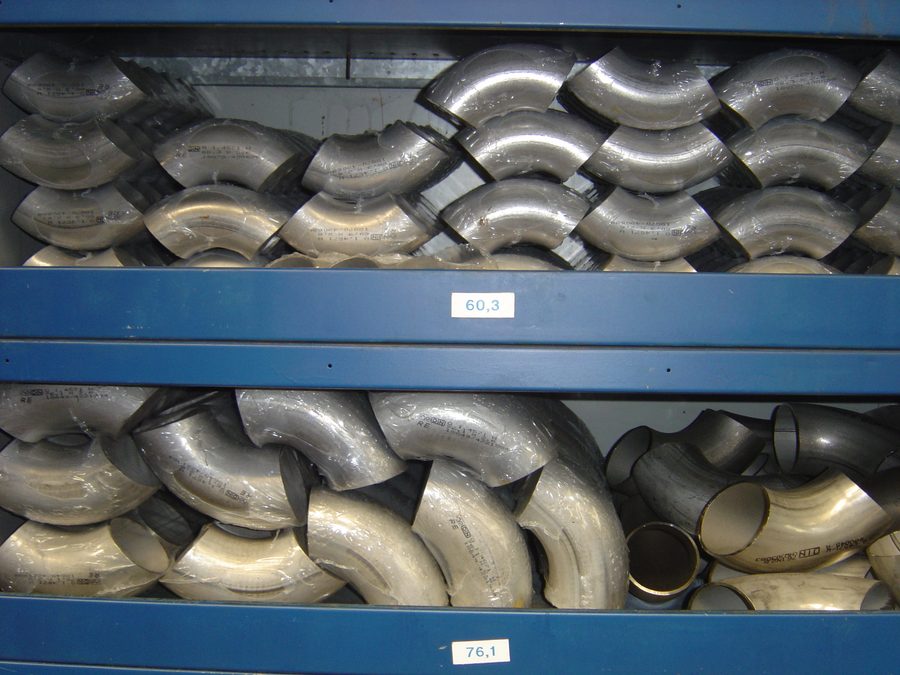
Standards: from DIN 2605 to EN 10253
The old German elbow standard DIN 2605 has been replaced by the European EN 10253. EN 10253 covers all butt-welding fittings (elbows, tees, reducers, caps) and is divided into four parts:
- Part 1: non-alloy steel without specific inspection requirements
- Part 2: non-alloy and alloy ferritic steel with specific inspection requirements (the standard in plant construction)
- Part 3: stainless steel without specific inspection requirements
- Part 4: stainless steel (austenitic and duplex) with specific inspection requirements
Old and new versions run in parallel in the trade; the installation dimensions are largely identical (small deviations in the radii of the smallest sizes were aligned with DIN 2605 in the revision of the standard).
Which part applies is decided by the material: for non-alloy and alloy steels part 2, for stainless steels part 4. Both parts are structured alike – their numbers are not.
Type A and type B: the pressure factor
The pressure factor X is the ratio of the pressure strength of the fitting to that of a straight pipe of the same dimensions, given as a percentage. It results from the forming: in bending, the inside of the bend is upset and the outside is stretched. The standard knows two versions for this.
Version
Type A – reduced pressure factor
The wall thickness corresponds to that of the connecting pipe, at the welding ends as on the body of the elbow. The fitting therefore does not reach the full strength of the straight pipe – the standard gives a pressure factor per design and wall thickness series. Type A is the standard commercial stock.
Version
Type B – full pressure resistance (wall thickness to EN 10253)
The elbow is made so that it reaches the strength of the straight pipe; for that the wall on the inside of the bend is thicker than at the welding end. Type B is chosen when the line is fully utilised in the calculation.
At the welding end both versions are the same – there the elbow fits the pipe, and only that counts for the weld. The difference is exactly one item: the pressure factor X for type A, the wall thickness on the inside of the bend for type B. For type B the pressure factor is, by definition, 100 %. Both values are given by the dimension finder on the respective material page for the selected size.
The historical translation for steel: DIN 2605-1 ≈ type A, DIN 2605-2 ≈ type B.
Designs 2D, 3D, 5D: the bend radius
The design says how tightly the elbow is curved: the bend radius is a multiple of the pipe outside diameter. The tighter the radius, the less space the elbow needs – and the greater flow resistance and erosion.
| Design | Radius | Properties |
|---|---|---|
| 2 (2D) | r ≈ 1 × d | shortest installation dimension, highest pressure loss, strongest erosion |
| 3 (3D) | r ≈ 1.5 × d | standard design in plant construction |
| 5 (5D) | r ≈ 2.5 × d | the most flow-favourable standard elbow, well suited to pigging |
Selection criteria (rules of thumb usual in the industry)
- Space: the smaller the radius, the more compact the installation – choose 2D only if 3D cannot be accommodated.
- Pressure loss/energy: the loss coefficient of a 90° elbow is noticeably higher for a tight radius (guide values: K ≈ 0.35–0.45 tight, K ≈ 0.25–0.30 at 1.5D). With many changes of direction this adds up in the pump design.
- Erosion/abrasion: tight radii deflect more sharply – choose a larger radius for media laden with solids or erosive media; on the outside of the bend the thinning of the wall is greater with a tight radius.
- Pigging: piggable lines need large radii (5D or elbows 3D/5D); tight elbows can block pigs.
- Stresses: tight radii have higher stress intensification factors – relevant under cyclic or thermal loading.
All K guide values on this page are non-binding orientation values from the technical literature; they vary by source, pipe roughness, Reynolds number and actual geometry. For the design the project-specific calculation and the manufacturers’ data are what governs.
Which radii the respective standard actually lists and which combinations of design and angle exist stands on the material pages – they do not coincide. Two examples: in EN 10253-4 there is no 45° elbow in design 2D, and the same standard additionally lists the metric designs D+100, 3DM and 5DM that do not exist in part 2.
45° or 90°?
A 45° elbow produces only about half the flow resistance of a 90° elbow (guide value K ≈ 0.15–0.20 against 0.25–0.30; equivalent pipe length about 16 instead of about 30 diameters). Typical 45° applications: changes in elevation, pump suction lines (gentle approach flow), abrasive media, gravity drains. Two 45° elbows with a spool piece can replace a 90° elbow (“dog-leg”), but cost additional welds.
Seamless or welded?
Seamless elbows (from seamless pipe) have no longitudinal seam; they are usual on the market for normal and thick-walled elbows up to about DN 600. Welded elbows are usual and more economical for thin walls and large diameters. Both manufacturing methods can be suitable for pressure-bearing applications if the applicable product and design standards are met – what decides are pressure factor (type A/B), material, wall thickness, testing and the applicable code, not the manufacturing method alone. In the marking, S stands for seamless, W for welded.
EN ↔ ASME: the most important differences
- ASME B16.9 standardises long radius (r = 1.5 × NPS) and short radius (r = 1.0 × NPS; formerly a standard of its own, ASME B16.28, today integrated in B16.9): functionally SR ≈ design 2D and LR ≈ design 3D. ASME B16.9 does not know a 5D standard design.
- The radii are similar but not identical: ASME calculates in inches via the NPS, EN defines metric radii.
- 45° elbows exist to ASME as long radius only.
- Wall thicknesses: ASME follows the schedule series (STD/XS/Sch 40 …), EN the wall thickness series 1–8 – part 2 lists them in a table of its own, part 4 names preferred values only in the annexes and therefore only for some of the diameters.
- LR is the default in the ASME environment (B31.3); SR has to be specified explicitly and checked by calculation.
And the dimensions?
This page deliberately names none. Bend radius, centre-to-end dimension, wall thickness series, pressure factor and limit deviation depend on the part of the standard and thus on the material. Both material pages show for every size a dimensioned drawing with the numerical values in the drawing, plus the complete dimension tables and the limit deviations to show and hide – elbows of steel to EN 10253-2 (with boiler tube bends, the material list and the scope of testing) and elbows of stainless steel to EN 10253-4 (with the points where part 4 deliberately departs from part 2: installation dimension F instead of W, roundness by D/T, sizes without a wall thickness series): elbows of steel and elbows of stainless steel.
Related fittings of the same standard: tees, reducers, caps and dished ends.
Technical basis: EN 10253-1 to -4 (formerly DIN 2605), ASME B16.9, ASME B31.3; K values from the technical literature as orientation. All information without guarantee – the current standard texts and the manufacturers’ technical data sheets always prevail. English version September 2026 of the German page.