Standards guide · Reducers
Reducers: concentric or eccentric, FOT/FOB and standards
A reducer is a butt-welding fitting that joins two pipelines of different nominal size. This page explains the concentric and the eccentric design, the installation positions FOT and FOB – and places the standards EN 10253 and DIN 2616.
- Standard
- EN 10253-2 / -4
- Replaces
- DIN 2616
- Designs
- concentric / eccentric
- Practical orientation
- usually 2–3 nominal size steps
Dimension finder + drawing · steel
Steel reducers – EN 10253-2
Dimensioned drawing for every size, concentric and eccentric switchable, with full dimension tables, pressure factor and tolerances.
Dimension finder + drawing · stainless steel
Stainless steel reducers – EN 10253-4
Dimensioned drawing for every size, concentric and eccentric switchable, with full dimension tables, pressure factor and tolerances.
What is a reducer?
A reducer is a butt-welding fitting that joins two pipelines of different nominal size. In practice, at most two or three nominal size steps are usually bridged per part; larger jumps are often solved by connecting several reducers in series. This is not a general rule of the standard – what governs are medium, flow, range and the applicable piping code.
Concentric or eccentric?
- Concentric: conical, both ends lie on one axis – the reduction runs evenly all round. Use: vertical lines and wherever the centre line is to run through.
- Eccentric: the two ends are offset against each other,
one side runs flat and straight through. Use: horizontal lines.
Advantage: the bottom or top edge of the line stays flush – so no
air pockets form in liquid lines and no liquid collects in gas lines. The
flat side can be placed deliberately on top or at the bottom:
- Flat side on top (FOT): frequent on horizontal pump suction lines – prevents a gas or vapour pocket collecting at the top, which can contribute to better suction conditions; the pump’s cavitation suitability (NPSH) has to be checked separately.
- Flat side on bottom (FOB): typical on pipe racks and in drain lines – the line rests squarely on its support and drains almost completely.
Why conical at all? Every abrupt narrowing of the cross-section constricts the flow: the jet does not follow the edge, becomes narrower than the cross-section itself and costs pressure – and in the constriction the pressure can drop locally so far that vapour bubbles form (cavitation). The conical transition of the reducer makes the change of cross-section gradual and keeps pressure loss and the tendency to cavitate small.
And why the installation position matters: with a concentric reducer in a horizontal line the axis stays at its level – at the bottom as at the top a step of half the difference in diameter results. Residual liquid stays in front of the lower step (it would have to run uphill to the small end), and a gas or vapour cushion collects at the upper one. The eccentric reducer puts the whole step on one side: flat side at the bottom (FOB) means a continuous floor – the line drains completely; flat side on top (FOT) means a continuous ceiling – no gas cushion. Hence the rule from installation practice: make reductions in horizontal lines eccentric – and where they have to be concentric, give the line a fall towards the larger nominal size so that the residual liquid can drain in front of the step.
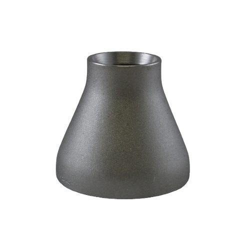
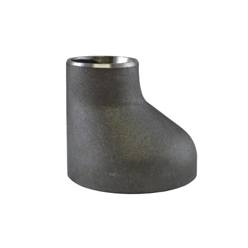
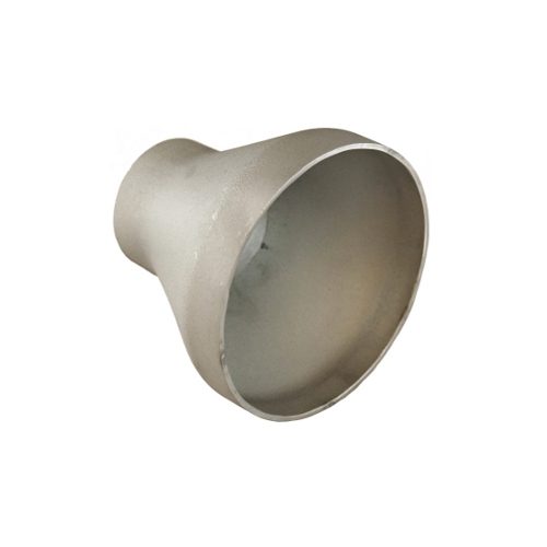
A frequent installation error: eccentric reducers installed without a look at the installation position. On horizontal suction lines FOT is usually right, for draining usually FOB – the correct orientation, however, depends on medium, direction of flow, venting and draining concept, solids content, pump manufacturer and piping code.
The length L is identical for the concentric and the eccentric version of the same size.
Standards: from DIN 2616 to EN 10253
Reducers of steel are standardised today in EN 10253-2 (type A = reduced, type B = full pressure resistance (wall thickness to EN 10253); commercial stock of reducers is frequently type B), of stainless steel in EN 10253-4 (for example 1.4541/1.4571, seamless or welded). The predecessor standard was DIN 2616. What the pressure factor means is explained on our elbow pages (German so far); the sister fitting of the same standard family is explained on the page Tees.
DIN 2616 part 1 and part 2: what was in which?
The two parts of the old DIN 2616 were – unlike often reported – not simply separated by design:
- DIN 2616 part 1 stood for the reduced pressure factor and contained eccentric reducers only – it corresponds to today's type A of EN 10253-2.
- DIN 2616 part 2 stood for the full pressure factor and contained concentric and eccentric reducers – today's type B.
A concentric version with reduced pressure factor therefore did not exist under DIN 2616. The two short formulas circulating on the market – “part 1/part 2 = pressure factor” on the one hand, “part 1 = eccentric, part 2 = concentric” on the other – each pick up only half the truth: the division followed the pressure factor, but concentric reducers occurred in part 2 only.
Tolerances (brief overview EN 10253)
Flow at least 80 % of the theoretical inside diameter; minus tolerance on wall thickness −12.5 %; length tolerances of the installation dimensions ±2 to ±5 mm depending on diameter. From 3.2 mm wall thickness with welding bevel (30°, root face 1.6 ± 0.8 mm). Marking of reducers always with both ends: D and T as well as D1 and T1.
EN ↔ ASME
ASME B16.9 standardises concentric and eccentric reducers with inch-based lengths (for example 8″ reducer: L = 152.4 mm). The EN lengths are practically identical for inch nominal sizes (152 mm); EN adds metric sizes. Material counterparts as for all butt-welding fittings: A234 WPB ↔ P235GH, A403 WP316Ti ↔ 1.4571. On US drawings the abbreviations FOT/FOB are usual – on the German market this corresponds to “gerade Seite oben/unten” (flat side on top/at the bottom).
Frequently asked questions about reducers
What does EN 10253-1 mean for reducers?
Part 1 stands for non-alloy steel without specific inspection requirements; the standard in plant construction is part 2. In addition, concentric or eccentric, both connection dimensions and the wall thicknesses have to be stated.
How is a reducer of P235GH to be classified?
P235GH is a non-alloy steel for pressure purposes; part of the standard, delivery condition and testing have to match both connecting pipes.
What does the failure pattern “wrong choice of design” mean?
A geometry that does not match the installation situation – possible consequences are installation problems, unfavourable pocket formation or a flow routing that was not intended.
Find the matching reducer directly
You already know design, dimensions and material? In the Zickwolff range you will find reducers for steel and stainless steel lines directly – our export team answers inquiries in English.
Technical basis: EN 10253-2 and -4 (formerly DIN 2616), ASME B16.9. All information without guarantee – the current standard texts and the manufacturers’ technical data sheets always prevail.