Standards guide · Stainless steel reducers
Stainless steel reducers: dimensions to EN 10253-4
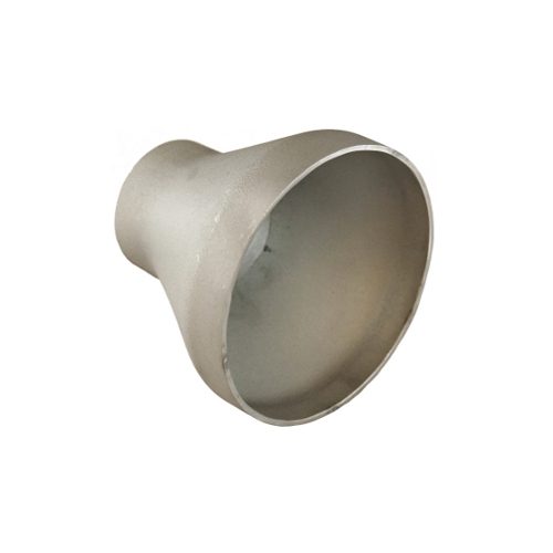
Reducers in stainless steel are covered by a part of the fittings standard of their own: EN 10253-4. It is built to the same pattern as part 2 for steel – and gives different figures throughout. This page carries those figures: pick the design, the large end, the small end and the wall thickness series, and the dimension finder shows the dimensioned drawing, the dimension table and the limit deviations for exactly that size. What separates the concentric from the eccentric reducer, and how type A differs from type B, is explained on the reducer basics page.
- Standard
- EN 10253-4:2025-10
- Material
- stainless steel
- Designs
- concentric / eccentric
- Dimension
- L
Dimension finder: dimensioned drawing for one specific size
Select design, large end, small end and wall thickness series – the drawing and the dimension table then show exactly that size, with the figures in the drawing itself instead of only the dimension letters. What separates the concentric from the eccentric design, and type A from type B, is on the reducer basics page. The dimension tables for the size pairs listed here are further down this page.
EN 10253-4 covers the greyed-out sizes. Our dimension overview lists them as order dimensions – see the table “Further deliverable dimensions” below.
Stainless steel reducer · concentric · 219.1 × 2.9 – 168.3 × 2.6 mm
Technical basis: DIN EN 10253-4:2025-10. Zickwolff has prepared this presentation for practical use, with our own structure, our own designations and a statement of what kind of value each figure is. The original standard governs normative requirements.
| Property | Value | Type of information |
|---|---|---|
| basic data | ||
| Wall thickness series | Series T2.9-2.6 | standard dimension |
| Availability | from stock or procured | trade information |
| nominal size (large end) | DN 200 | assignment |
| nominal size (small end) | DN 150 | assignment |
| connecting dimensions The dimensions at the welding ends that govern the joint with the pipe that follows. | ||
| outside diameter (large end) D | 219.1 mm | standard dimension |
| wall thickness (large end) T | 2.9 mm | standard dimension |
| inside diameter (large end) | 213.3 mm | calculated |
| outside diameter (small end) D1 | 168.3 mm | standard dimension |
| wall thickness (small end) T1 | 2.6 mm | standard dimension |
| inside diameter (small end) | 163.1 mm | calculated |
| installation dimensions The dimensions that determine the installation space. | ||
| centre-to-end dimension L | 152 mm | standard dimension |
Without an entry in the “Type of information” column: standard dimension. A dimension that EN 10253-4 specifies for this size.
Where exactly it is measured
- outside diameter (large end) D
- measured across the edge at the welding ends
- outside diameter (small end) D1
- measured across the edge at the welding ends
- inside diameter (large end)
- ID = D − 2T
- inside diameter (small end)
- ID1 = D1 − 2T1
- centre-to-end dimension L
- overall length across both welding ends
Tolerances (limit deviations): what range the standard permits
For each dimension the range that EN 10253-4 permits is given – minimum and maximum instead of the deviation that would first have to be worked out. In the drawing this is shortened to tolerance – the word everyone uses in practice. In technical terms the two values given are the limit dimensions of the dimension, their distance is the tolerance and the deviations from the nominal size are the limit deviations. The basis is clause 11.2 with Table 8 and Table 9, and clause 11.3 – where the standard specifies nothing, that is stated.
These dimensions have two limit deviations – which one applies depends on the specific part
For the following dimensions the standard specifies two limit deviations. Which one applies does not depend on the nominal size but on the specific part. Both cases are therefore written out.
This answer determines: out-of-roundness Ov.
out-of-roundness Ov – calculated as 100 · (Dmax − Dmin)/D, largest and smallest outside diameter in the same cross-section – at each welding end the diameter of that end counts
At which weld end is the out-of-roundness measured? (a reducer has two weld ends of different diameter: the large end with D and the small end with D1. The standard gives the permissible out-of-roundness as a percentage of the diameter – and that diameter is the one of the end being measured. The two ends can therefore fall into different classes. What is measured, in one and the same cross-section, is the largest outside diameter minus the smallest)
- at the large end (⌀ D) out-of-roundness Up to D 406.4 no separate limit is specified – but Dmax and Dmin must each lie within the limit deviation of the diameter, and that limits the difference by itself.
- at the small end (⌀ D1) out-of-roundness Up to D1 406.4 no separate limit is specified – but Dmax and Dmin must each lie within the limit deviation of the diameter, and that limits the difference by itself.
- I don't know both cases remain
What the standard specifies beyond the dimensions in the drawing
The following requirements are not tied to any dimension in the drawing. They are set out here in the structure of the standard, under its own headings. The label on each line says what kind of information it is – a dimension from the standard, a statement of the standard, an acceptance criterion on the finished part, or a manufacturing requirement.
diameter
| inside diameter at any point acceptance criterion | at least 130.48 mm (80 % of ID1) – The reducer has two connecting inside diameters – the small end governs: no restriction below 80 % of its inside diameter (ID1 = D1 − 2T1). Where the two ends differ in size the standard does not state the reference explicitly – this is an interpretation, not an explicit statement of the standard. |
|---|
Every dimension has its reason – whoever knows why they measure, measures better.
out-of-roundness
| out-of-roundness Ov standard value | at the large end (⌀ D): Up to D 406.4 no separate limit is specified – but Dmax and Dmin must each lie within the limit deviation of the diameter, and that limits the difference by itself. · at the small end (⌀ D1): Up to D1 406.4 no separate limit is specified – but Dmax and Dmin must each lie within the limit deviation of the diameter, and that limits the difference by itself. |
|---|
limit deviations for the wall thickness
| wall thickness at the fitting body statement of the standard | At the fitting body no upper limit deviation of the wall thickness is defined (option 19: as ordered). |
|---|
limit deviations for selected dimensions and form tolerance
| fitting geometry (squareness and alignment deviation) standard value | at most 2.19 mm (1 % of D, at least 1 mm) |
|---|
The standard checks all limit deviations for the fitting geometry in the same position of the fitting (figure 9).
corrugation
| mean height of the corrugation hm acceptance criterion | at most 6.57 mm (3 % of D, at most 25 mm) |
|---|---|
| length of the corrugation LE acceptance criterion | at least 15 times of hm |
end preparation
| end preparation design rule | For ordered wall thicknesses below 3.2 mm the ends may be square, at the manufacturer's discretion. |
|---|---|
| rework: outside bevel angle design rule | at most 30° |
| rework: inside bevel angle design rule | at most 18° |
| freedom from burrs at the ends design rule | The ends of the fitting shall be free from dangerous burrs. |
Sources of the limit deviations (16 entries)
- out-of-roundness (at the large end (⌀ D)) – 11.2.2
- out-of-roundness (at the small end (⌀ D1)) – 11.2.2
- inside diameter at any point – 11.2.1.2
- wall thickness at the fitting body – 11.2.3 NOTE
- fitting geometry (squareness and alignment deviation) – 11.2.4 and Figure 15
- mean height of the corrugation – 11.2.5
- length of the corrugation – 11.2.5
- end preparation – 11.3
- rework: outside bevel angle – 11.3
- rework: inside bevel angle – 11.3
- freedom from burrs at the ends – 11.3
- outside diameter (large end) – 11.2.1.1
- wall thickness (large end) – Table 8
- outside diameter (small end) – 11.2.1.1
- wall thickness (small end) – Table 8
- centre-to-end dimension – Table 9
This information does not replace the standard itself. Only the limit deviations for the size selected here are reproduced. In full – for all dimensions and fittings of the standard – they are given in DIN EN 10253-4:2025-10, clause 11.2 with Table 8 and Table 9, and clause 11.3. Where to obtain it: DIN Media.
Why limit deviations exist at all and how to read them is explained on a page of its own: Tolerances and limit deviations.
Not in the dimension finder: ⌀ 57 – 26.9, ⌀ 57 – 33.7, ⌀ 57 – 42.4, ⌀ 57 – 48.3, ⌀ 108 – 48.3, ⌀ 108 – 60.3, ⌀ 108 – 76.1, ⌀ 108 – 88.9, ⌀ 133 – 60.3, ⌀ 133 – 76.1, ⌀ 133 – 88.9, ⌀ 133 – 114.3, ⌀ 159 – 76.1, ⌀ 159 – 88.9, ⌀ 159 – 114.3, ⌀ 159 – 139.7, ⌀ 559 – 355.6, ⌀ 559 – 406.4, ⌀ 559 – 457, ⌀ 559 – 508 – No dimension row arises for these combinations: for one of the two diameters the standard gives no wall thickness series – without a wall thickness there is neither a scale drawing nor a complete dimension row.
Dimensions are nominal dimensions to EN 10253-4 and do not replace the data sheet of the actual item. No statement about pressure or temperature suitability and no statement about the material. L is the overall length across both welding ends. The design makes no difference to the dimensions. Direct link to this size
How to measure correctly
A reducer is identified by five measurements: outside diameter and wall thickness at the large end (D, T), the same at the small end (D1, T1), and the overall length L across both welding ends. Measure the diameters across the edge of the welding ends. Whether the part is concentric or eccentric is seen, not measured: on an eccentric reducer one side runs straight through.
- outside diameter (large end) D
- measured across the edge at the welding ends
- outside diameter (small end) D1
- measured across the edge at the welding ends
- centre-to-end dimension L
- overall length across both welding ends
A measured value rarely matches the table exactly. The dimension finder on this page shows the limit deviations of EN 10253-4 for every size.
Concentric and eccentric
On the concentric reducer both welding ends lie on a common centre line – the reduction runs evenly all round. On the eccentric reducer the two axes are offset parallel to each other: one generatrix runs straight through, and on that side the part stays flush with the line.
The standard lists both designs in one dimension table (Table A.9): large end D, small end D1, wall thicknesses T and T1 and the overall length L are identical – even the weight does not differ. That is why the design is, in the dimension finder above, a switch on the drawing and not a size selection of its own. Only the pressure factor depends on the design; the tables for it are given further down.
When which design is installed – straight generatrix at the top or at the bottom – is explained on the basics page on reducers.
Type A and type B: the pressure factor
At the conical transition a reducer carries the internal pressure differently from the straight pipe. The standard describes this with two versions:
Version
Type A – reduced pressure factor
Wall thickness at the fitting body as at the welding ends. How much internal pressure the part carries compared with the straight pipe is stated by the pressure factor X in per cent – separately for both designs, in the tables below.
Version
Type B – full pressure resistance (standard: “for use at full service pressure”)
Increased wall thickness at the fitting body, designed for the same internal pressure as the straight pipe. The standard verifies the wall thickness needed according to Annex B; it is listed in Annex D.
The pressure factors on this page are calculated by us – via the equations of Annex B, clause B.4.5, with an arithmetical cross-check (reference in the standard: Annex C).
What this page does not show yet. The increased wall thickness of type B is not given here. We have not yet checked the associated verification route (Annex B, B.5.4) against the values of Annex D – and an unverified number would look on this page exactly like a verified one. It will be added as soon as it is substantiated.
The overall length L
The reducer has exactly one overall dimension: L, the length across both welding ends. It depends only on the large end – all small ends of the same run share the same overall length.
The standard dimensions nothing more at the transition: neither the cone angle nor the length of the cylindrical end sections. The drawing above says so in its footer – drawn is the usual shape, dimensioned is what the standard specifies.
The permissible deviations of L are given in EN 10253-4, Table 9; the drawing above shows them in tolerance mode as a second line at the dimension.
Limit deviations and out-of-roundness – per welding end
The drawing above carries the complete tolerance block – here the points that are particular to the reducer:
- Each end counts with its own diameter. The standard measures “the corresponding outside diameters (D–D1) … at the welding ends” (clause 11.2.1.1). For the small end, the diameter and wall thickness limit deviations therefore apply with D1 and T1 – not with the values of the large end. For a 711 – 508 the large end can thus lie in a different band from the small end.
- No out-of-roundness limit at the fitting body. The 4 % at the body applies, according to clause 11.2.2, only “to elbows and 180° elbows”. At the welding ends the graduation of Part 4 applies – for each end with its own diameter: up to ⌀ 406.4 included in the diameter limit deviation, above that 2 % at a ratio D/T up to 100, otherwise by agreement.
- No form tolerance P. In the overall dimension table it is expressly listed as a form tolerance for elbows.
Above ⌀ 610 mm the wall thickness limit deviations depend on whether the fitting is seamless or welded – again for each end with its own diameter and wall thickness. Below that, the distinction makes no difference to the dimensions.
Which sizes this page shows – and where they come from
For each run, the dimension table of the standard names a range of possible small ends (“57 × 26.9 to 48.3”) – which sizes lie within it is enumerated one by one by the normative Annex C. That enumeration is the source of the size pairs on this page.
One group deserves a note:
- Five runs remain without a drawing and without a dimension row (⌀ 57: L 76 mm, small ends 26.9 to 48.3 mm; ⌀ 108: L 102 mm, small ends 48.3 to 88.9 mm; ⌀ 133: L 127 mm, small ends 60.3 to 114.3 mm; ⌀ 159: L 140 mm, small ends 76.1 to 139.7 mm; ⌀ 559: L 508 mm, small ends 355.6 to 508 mm). The dimension table of the standard names an overall length and a range of small ends for them, but Annex C does not enumerate the pairs, and the wall thickness series of the standard (Table 7) do not carry these diameters – without a wall thickness there is neither a drawing to scale nor a complete dimension row. So only the values the standard gives are listed here: overall length and range.
We spell this out instead of silently smoothing it over: a gap that can be seen is something different from a guessed number.
Dimension tables for reducers in stainless steel: 43 size pairs
Zickwolff dimension overview (standard reference EN 10253-4) – one row per size pair of large and small end, the wall thicknesses of each series side by side. They apply to the concentric as well as the eccentric design. If you need a dimensioned drawing for one of these sizes, the dimension finder at the top of this page has it.
Nominal dimensions Pressure factor outside the preferred series Further deliverable dimensions
Nominal dimensions by wall thickness series
T is the wall thickness at the large end, T1 the one at the small end, both belonging to the same series number. L is the overall length across both welding ends.
Show full table · more than 30 rows
| Doutside diameter (large end) in mm | DNnominal size (large end) | D1outside diameter (small end) in mm | DN1nominal size (small end) in DN | Lcentre-to-end dimension in mm | Series 2 | Series 3 | Series 5 | |||
|---|---|---|---|---|---|---|---|---|---|---|
| T – large end wall thickness in mm, series 2 | T1 – small end wall thickness in mm, series 2 | T – large end wall thickness in mm, series 3 | T1 – small end wall thickness in mm, series 3 | T – large end wall thickness in mm, series 5 | T1 – small end wall thickness in mm, series 5 | |||||
| 26.9 | 20 | 17.2 | 10 | 38 | no wall thickness for the small end in this series | no wall thickness for either end in this series | 2.3 | 2 | ||
| 26.9 | 20 | 21.3 | 15 | 38 | no wall thickness for the small end in this series | no wall thickness for either end in this series | 2.3 | 2 | ||
| 33.7 | 25 | 21.3 | 15 | 51 | no wall thickness for the small end in this series | no wall thickness for the small end in this series | 2.6 | 2 | ||
| 33.7 | 25 | 26.9 | 20 | 51 | 2 | 2 | no wall thickness for the small end in this series | 2.6 | 2.3 | |
| 42.4 | 32 | 21.3 | 15 | 51 | no wall thickness for the small end in this series | no wall thickness for the small end in this series | 2.6 | 2 | ||
| 42.4 | 32 | 26.9 | 20 | 51 | 2 | 2 | no wall thickness for the small end in this series | 2.6 | 2.3 | |
| 42.4 | 32 | 33.7 | 25 | 51 | 2 | 2 | we do not show this wall thickness series at present | 2.6 | 2.6 | |
| 48.3 | 40 | 26.9 | 20 | 64 | 2 | 2 | no wall thickness for the small end in this series | 2.6 | 2.3 | |
| 48.3 | 40 | 33.7 | 25 | 64 | 2 | 2 | we do not show this wall thickness series at present | 2.6 | 2.6 | |
| 48.3 | 40 | 42.4 | 32 | 64 | 2 | 2 | we do not show this wall thickness series at present | 2.6 | 2.6 | |
| 60.3 | 50 | 26.9 | 20 | 76 | 2 | 2 | no wall thickness for the small end in this series | we do not show this wall thickness series at present | ||
| 60.3 | 50 | 33.7 | 25 | 76 | 2 | 2 | we do not show this wall thickness series at present | 2.9 | 2.6 | |
| 60.3 | 50 | 42.4 | 32 | 76 | 2 | 2 | we do not show this wall thickness series at present | 2.9 | 2.6 | |
| 60.3 | 50 | 48.3 | 40 | 76 | 2 | 2 | we do not show this wall thickness series at present | 2.9 | 2.6 | |
| 76.1 | 65 | 33.7 | 25 | 89 | we do not show this wall thickness series at present | 2.3 | 2.3 | we do not show this wall thickness series at present | ||
| 76.1 | 65 | 42.4 | 32 | 89 | 2 | 2 | we do not show this wall thickness series at present | 2.9 | 2.6 | |
| 76.1 | 65 | 48.3 | 40 | 89 | 2 | 2 | we do not show this wall thickness series at present | 2.9 | 2.6 | |
| 76.1 | 65 | 60.3 | 50 | 89 | we do not show this wall thickness series at present | we do not show this wall thickness series at present | 2.9 | 2.9 | ||
| 88.9 | 80 | 42.4 | 32 | 89 | 2.3 | 2 | we do not show this wall thickness series at present | 3.2 | 2.6 | |
| 88.9 | 80 | 48.3 | 40 | 89 | 2.3 | 2 | we do not show this wall thickness series at present | 3.2 | 2.6 | |
| 88.9 | 80 | 60.3 | 50 | 89 | 2.3 | 2 | we do not show this wall thickness series at present | 3.2 | 2.9 | |
| 88.9 | 80 | 76.1 | 65 | 89 | 2.3 | 2 | 2.6 | 2.3 | 3.2 | 2.9 |
| 114.3 | 100 | 48.3 | 40 | 102 | 2.6 | 2 | we do not show this wall thickness series at present | we do not show this wall thickness series at present | ||
| 114.3 | 100 | 60.3 | 50 | 102 | 2.6 | 2 | we do not show this wall thickness series at present | 3.6 | 2.9 | |
| 114.3 | 100 | 76.1 | 65 | 102 | we do not show this wall thickness series at present | we do not show this wall thickness series at present | 3.6 | 2.9 | ||
| 114.3 | 100 | 88.9 | 80 | 102 | 2.6 | 2.3 | we do not show this wall thickness series at present | 3.6 | 3.2 | |
| 139.7 | 125 | 76.1 | 65 | 127 | we do not show this wall thickness series at present | we do not show this wall thickness series at present | 4 | 2.9 | ||
| 139.7 | 125 | 88.9 | 80 | 127 | 2.6 | 2.3 | we do not show this wall thickness series at present | 4 | 3.2 | |
| 139.7 | 125 | 114.3 | 100 | 127 | 2.6 | 2.6 | we do not show this wall thickness series at present | 4 | 3.6 | |
| 168.3 | 150 | 88.9 | 80 | 140 | 2.6 | 2.3 | we do not show this wall thickness series at present | 4.5 | 3.2 | |
| 168.3 | 150 | 114.3 | 100 | 140 | 2.6 | 2.6 | we do not show this wall thickness series at present | 4.5 | 3.6 | |
| 168.3 | 150 | 139.7 | 125 | 140 | 2.6 | 2.6 | we do not show this wall thickness series at present | 4.5 | 4 | |
standard dimension: D, D1, L, T, T1 · assignment: DN, DN1
Where a series column carries no figure, the digit at the dash says why – mostly the standard, in one case us:
–2 EN 10253-4 lists no wall thickness of this series for this small end. 10 cells
–3 EN 10253-4 lists a wall thickness of this series for neither of the two ends. 2 cells
–5 EN 10253-4 does list a wall thickness of this series for this size pair; our dimension overview does not show it at present. 29 cells
Pressure factor by design and series
The pressure factor X says what proportion of the pipe pressure a reducer of this size carries. The values are those of tables C.3 (concentric) and C.4 (eccentric) of the standard. We additionally recalculated every cell through the equations of Annex B and matched them in full. α is the largest opening angle for which the row applies – that too is how the standard states it.
Show full table · more than 30 rows
| Doutside diameter (large end) in mm | D1outside diameter (small end) in mm | α conc.largest opening angle, concentric | α ecc.largest opening angle, eccentric | Series 2 | Series 3 | Series 5 | |||
|---|---|---|---|---|---|---|---|---|---|
| conc. – pressure factor concentric in per cent, series 2 | ecc. – pressure factor eccentric in per cent, series 2 | conc. – pressure factor concentric in per cent, series 3 | ecc. – pressure factor eccentric in per cent, series 3 | conc. – pressure factor concentric in per cent, series 5 | ecc. – pressure factor eccentric in per cent, series 5 | ||||
| 26.9 | 17.2 | 12° | 27° | no wall thickness for the small end in this series | no wall thickness for either end in this series | 100 | 100 | ||
| 26.9 | 21.3 | 8° | 15° | no wall thickness for the small end in this series | no wall thickness for either end in this series | 100 | 100 | ||
| 33.7 | 21.3 | 12° | 24° | no wall thickness for the small end in this series | no wall thickness for the small end in this series | 100 | 100 | ||
| 33.7 | 26.9 | 7° | 13° | 100 | 100 | no wall thickness for the small end in this series | 100 | 100 | |
| 42.4 | 21.3 | 19° | 42° | no wall thickness for the small end in this series | no wall thickness for the small end in this series | 100 | 97 | ||
| 42.4 | 26.9 | 15° | 30° | 100 | 100 | no wall thickness for the small end in this series | 100 | 100 | |
| 42.4 | 33.7 | 9° | 16° | 100 | 100 | we do not show this wall thickness series at present | 100 | 100 | |
| 48.3 | 26.9 | 16° | 28° | 100 | 100 | no wall thickness for the small end in this series | 100 | 100 | |
| 48.3 | 33.7 | 10° | 19° | 100 | 100 | we do not show this wall thickness series at present | 100 | 100 | |
| 48.3 | 42.4 | 6° | 8° | 100 | 100 | we do not show this wall thickness series at present | 100 | 100 | |
| 60.3 | 26.9 | 21° | 36° | 100 | 94 | no wall thickness for the small end in this series | we do not show this wall thickness series at present | ||
| 60.3 | 33.7 | 16° | 29° | 100 | 99 | we do not show this wall thickness series at present | 100 | 100 | |
| 60.3 | 42.4 | 11° | 20° | 100 | 100 | we do not show this wall thickness series at present | 100 | 100 | |
| 60.3 | 48.3 | 7° | 13° | 100 | 100 | we do not show this wall thickness series at present | 100 | 100 | |
| 76.1 | 33.7 | 23° | 42° | we do not show this wall thickness series at present | 100 | 87 | we do not show this wall thickness series at present | ||
| 76.1 | 42.4 | 18° | 34° | 100 | 93 | we do not show this wall thickness series at present | 100 | 97 | |
| 76.1 | 48.3 | 15° | 27° | 100 | 98 | we do not show this wall thickness series at present | 100 | 100 | |
| 76.1 | 60.3 | 9° | 15° | we do not show this wall thickness series at present | we do not show this wall thickness series at present | 100 | 100 | ||
| 88.9 | 42.4 | 26° | 50° | 99 | 77 | we do not show this wall thickness series at present | 100 | 80 | |
| 88.9 | 48.3 | 22° | 44° | 100 | 84 | we do not show this wall thickness series at present | 100 | 87 | |
| 88.9 | 60.3 | 16° | 30° | 100 | 96 | we do not show this wall thickness series at present | 100 | 99 | |
| 88.9 | 76.1 | 7° | 13° | 100 | 100 | 100 | 100 | 100 | 100 |
| 114.3 | 48.3 | 31° | 60° | 95 | (62) | we do not show this wall thickness series at present | we do not show this wall thickness series at present | ||
| 114.3 | 60.3 | 26° | 51° | 98 | (74) | we do not show this wall thickness series at present | 100 | 78 | |
| 114.3 | 76.1 | 18° | 37° | we do not show this wall thickness series at present | we do not show this wall thickness series at present | 100 | 93 | ||
| 114.3 | 88.9 | 13° | 24° | 100 | 99 | we do not show this wall thickness series at present | 100 | 100 | |
| 139.7 | 76.1 | 25° | 43° | we do not show this wall thickness series at present | we do not show this wall thickness series at present | 100 | 86 | ||
| 139.7 | 88.9 | 20° | 35° | 100 | 90 | we do not show this wall thickness series at present | 100 | 93 | |
| 139.7 | 114.3 | 10° | 18° | 100 | 100 | we do not show this wall thickness series at present | 100 | 100 | |
| 168.3 | 88.9 | 27° | 48° | 95 | (76) | we do not show this wall thickness series at present | 98 | 80 | |
| 168.3 | 114.3 | 19° | 34° | 99 | 90 | we do not show this wall thickness series at present | 100 | 94 | |
| 168.3 | 139.7 | 9° | 18° | 100 | 100 | we do not show this wall thickness series at present | 100 | 100 | |
standard dimension: D, D1 · standard value: α, X
( ) Values in brackets apply only if the cylindrical end lengths reach the minimum values to Annex B, or if the reducer sits between pipes of wall thickness T and T1 respectively – that is how the standard states it. 3 cells
Where a series column carries no figure, the digit at the dash says why – mostly the standard, in one case us:
–2 EN 10253-4 lists no wall thickness of this series for this small end. 10 cells
–3 EN 10253-4 lists a wall thickness of this series for neither of the two ends. 2 cells
–5 EN 10253-4 does list a wall thickness of this series for this size pair; our dimension overview does not show it at present. 29 cells
Dimensions outside the preferred series
EN 10253-4 pairs diameter and wall thickness through a series number. The sizes below we carry with a wall thickness that is in no series for that size – or with two wall thicknesses that are each in the standard, but not in the same series. The dimensions are established in the same way as in the grid above. Where the standard gives its values through the series number, the cell stays empty.
Show full table · more than 40 rows
| Doutside diameter (large end) in mm | D1outside diameter (small end) in mm | nominal size (large end) in DN | nominal size (small end) in DN | Twall thickness (large end) in mm | T1wall thickness (small end) in mm | inside diameter (large end) in mm | inside diameter (small end) in mm | Lcentre-to-end dimension in mm | outside diameter to wall thickness ratio | outside diameter to wall thickness ratio at the small end |
|---|---|---|---|---|---|---|---|---|---|---|
| 21.3 | 17.2 | 15 | 10 | 2 | 1.6 | 17.3 | 14 | 28 | 10.65 | 10.75 |
| 21.3 | 17.2 | 15 | 10 | 2 | 1.8 | 17.3 | 13.6 | 28 | 10.65 | 9.56 |
| 26.9 | 17.2 | 20 | 10 | 2 | 1.8 | 22.9 | 13.6 | 38 | 13.45 | 9.56 |
| 26.9 | 21.3 | 20 | 15 | 2 | 2 | 22.9 | 17.3 | 38 | 13.45 | 10.65 |
| 33.7 | 21.3 | 25 | 15 | 2 | 2 | 29.7 | 17.3 | 51 | 16.85 | 10.65 |
| 33.7 | 21.3 | 25 | 15 | 2.6 | 2.6 | 28.5 | 16.1 | 51 | 12.96 | 8.19 |
| 42.4 | 21.3 | 32 | 15 | 2 | 2 | 38.4 | 17.3 | 51 | 21.2 | 10.65 |
| 42.4 | 33.7 | 32 | 25 | 2.6 | 2.3 | 37.2 | 29.1 | 51 | 16.31 | 14.65 |
| 48.3 | 21.3 | 40 | 15 | 2 | 2 | 44.3 | 17.3 | 64 | 24.15 | 10.65 |
| 48.3 | 33.7 | 40 | 25 | 3.2 | 3.2 | 41.9 | 27.3 | 64 | 15.09 | 10.53 |
| 76.1 | 33.7 | 65 | 25 | 2.3 | 2 | 71.5 | 29.7 | 89 | 33.09 | 16.85 |
| 76.1 | 42.4 | 65 | 32 | 2.3 | 2 | 71.5 | 38.4 | 89 | 33.09 | 21.2 |
| 76.1 | 48.3 | 65 | 40 | 2.3 | 2 | 71.5 | 44.3 | 89 | 33.09 | 24.15 |
| 76.1 | 60.3 | 65 | 50 | 2.3 | 2 | 71.5 | 56.3 | 89 | 33.09 | 30.15 |
| 88.9 | 42.4 | 80 | 32 | 2.6 | 2 | 83.7 | 38.4 | 89 | 34.19 | 21.2 |
| 88.9 | 48.3 | 80 | 40 | 2.6 | 2 | 83.7 | 44.3 | 89 | 34.19 | 24.15 |
| 88.9 | 60.3 | 80 | 50 | 2.6 | 2 | 83.7 | 56.3 | 89 | 34.19 | 30.15 |
| 88.9 | 76.1 | 80 | 65 | 2.3 | 2.3 | 84.3 | 71.5 | 89 | 38.65 | 33.09 |
| 114.3 | 60.3 | 100 | 50 | 2.3 | 2 | 109.7 | 56.3 | 102 | 49.7 | 30.15 |
| 114.3 | 60.3 | 100 | 50 | 2.6 | 2.3 | 109.1 | 55.7 | 102 | 43.96 | 26.22 |
| 114.3 | 76.1 | 100 | 65 | 2.3 | 2 | 109.7 | 72.1 | 102 | 49.7 | 38.05 |
| 114.3 | 76.1 | 100 | 65 | 2.6 | 2.3 | 109.1 | 71.5 | 102 | 43.96 | 33.09 |
| 114.3 | 88.9 | 100 | 80 | 2.3 | 2 | 109.7 | 84.9 | 102 | 49.7 | 44.45 |
| 114.3 | 88.9 | 100 | 80 | 2.6 | 2.6 | 109.1 | 83.7 | 102 | 43.96 | 34.19 |
| 139.7 | 60.3 | 125 | 50 | 2.9 | 2.3 | 133.9 | 55.7 | 127 | 48.17 | 26.22 |
| 139.7 | 76.1 | 125 | 65 | 2.6 | 2.3 | 134.5 | 71.5 | 127 | 53.73 | 33.09 |
| 139.7 | 76.1 | 125 | 65 | 2.9 | 2.3 | 133.9 | 71.5 | 127 | 48.17 | 33.09 |
| 139.7 | 88.9 | 125 | 80 | 2.6 | 2 | 134.5 | 84.9 | 127 | 53.73 | 44.45 |
| 139.7 | 114.3 | 125 | 100 | 2.6 | 2.3 | 134.5 | 109.7 | 127 | 53.73 | 49.7 |
| 139.7 | 114.3 | 125 | 100 | 2.9 | 2.6 | 133.9 | 109.1 | 127 | 48.17 | 43.96 |
| 139.7 | 114.3 | 125 | 100 | 4 | 2.6 | 131.7 | 109.1 | 127 | 34.92 | 43.96 |
| 168.3 | 76.1 | 150 | 65 | 2.6 | 2.3 | 163.1 | 71.5 | 140 | 64.73 | 33.09 |
| 168.3 | 76.1 | 150 | 65 | 2.9 | 2.3 | 162.5 | 71.5 | 140 | 58.03 | 33.09 |
| 168.3 | 88.9 | 150 | 80 | 2.9 | 2.3 | 162.5 | 84.3 | 140 | 58.03 | 38.65 |
| 168.3 | 114.3 | 150 | 100 | 2.6 | 2.3 | 163.1 | 109.7 | 140 | 64.73 | 49.7 |
| 168.3 | 114.3 | 150 | 100 | 2.9 | 2.6 | 162.5 | 109.1 | 140 | 58.03 | 43.96 |
| 168.3 | 139.7 | 150 | 125 | 2.9 | 2.6 | 162.5 | 134.5 | 140 | 58.03 | 53.73 |
| 219.1 | 114.3 | 200 | 100 | 2.9 | 2.6 | 213.3 | 109.1 | 152 | 75.55 | 43.96 |
| 219.1 | 139.7 | 200 | 125 | 2.9 | 2.6 | 213.3 | 134.5 | 152 | 75.55 | 53.73 |
| 219.1 | 139.7 | 200 | 125 | 2.9 | 2.9 | 213.3 | 133.9 | 152 | 75.55 | 48.17 |
| 219.1 | 139.7 | 200 | 125 | 3 | 3 | 213.1 | 133.7 | 152 | 73.03 | 46.57 |
| 219.1 | 168.3 | 200 | 150 | 2.9 | 2.6 | 213.3 | 163.1 | 152 | 75.55 | 64.73 |
| 219.1 | 168.3 | 200 | 150 | 2.9 | 2.9 | 213.3 | 162.5 | 152 | 75.55 | 58.03 |
| 219.1 | 168.3 | 200 | 150 | 3 | 3 | 213.1 | 162.3 | 152 | 73.03 | 56.1 |
| 273 | 168.3 | 250 | 150 | 3 | 3 | 267 | 162.3 | 178 | 91 | 56.1 |
| 273 | 219.1 | 250 | 200 | 3 | 3 | 267 | 213.1 | 178 | 91 | 73.03 |
| 273 | 219.1 | 250 | 200 | 4 | 4 | 265 | 211.1 | 178 | 68.25 | 54.78 |
| 323.9 | 219.1 | 300 | 200 | 3 | 3 | 317.9 | 213.1 | 203 | 107.97 | 73.03 |
| 323.9 | 273 | 300 | 250 | 3 | 3 | 317.9 | 267 | 203 | 107.97 | 91 |
Further deliverable dimensions (7)
| Doutside diameter (large end) in mm | D1outside diameter (small end) in mm | Twall thickness (large end) in mm | T1wall thickness (small end) in mm |
|---|---|---|---|
| 219.1 | 88.9 | 6.3 | 3.2 |
| 219.1 | 88.9 | 8 | 5.6 |
| 219.1 | 88.9 | 12.5 | 8 |
| 273 | 114.3 | 2 | 2 |
| 273 | 139.7 | 2 | 2 |
| 355.6 | 323.9 | 4 | 4 |
| 406.4 | 323.9 | 4 | 4 |
Order dimensions and values calculated by us; deliverable from stock or procured, availability on request. Limit deviations and figures from the standard: see the main table and the standard itself.
The dimensions given are nominal dimensions. The text of the standard prevails. The German edition DIN EN 10253-4:2025-10 reproduces the European version EN 10253-4:2025.
Stainless reducers by dimension – ask our warehouse
You know both ends? Send us the two outside diameters with their wall thicknesses and the design, together with the material grade and the inspection document required. Our export team answers in English, with price, availability and certificate.
Send an inquiryHow this data is compiled. This page does not reproduce a standard. It shows the dimensions you need for an enquiry, an order and installation – for sizes we supply, checked against documents from manufacturing works and suppliers and against our own range. Each value states what kind of value it is: specified by the standard, calculated by us or customary in the trade. The currently valid standard is binding. It is available from DIN Media or from your national standards body. How we select our sources and keep them up to date: About this knowledge.
Technical basis: DIN EN 10253-4:2025-10 (butt-welding fittings of stainless steel), EN 10253-2, EN 10204. All information without guarantee – the current standard texts and the manufacturers’ technical data sheets always prevail.