Standards guide · Flanges
Flange types international: ASME styles and their EN 1092-1 equivalents
Weld neck, slip-on, lap joint – anyone working with US specifications, imported plant or mixed projects meets the flange styles of ASME B16.5. This page explains the internationally used flange styles and maps them to the type numbers of EN 1092-1 – including the most common selection question, weld neck or slip-on, the facing codes beyond RF and a quick DIN ↔ ASTM material cross-reference.
- US standard
- ASME B16.5
- EN counterpart
- EN 1092-1
- Styles
- WN / SO / threaded / SW / LJ / blind
- Materials
- ASTM ↔ DIN/EN
What this page covers
EN 1092-1 identifies flange designs by type numbers (type 01, 02, 05, 11, 13). This page explains the internationally used styles of ASME B16.5 and maps them to those EN types – essential for anyone dealing with US specifications, imported plant or mixed projects. The matching dimension tables: flange dimensions PN 6 to PN 40 (EN 1092-1); ASME B16.5 tables will follow in English shortly.
On narrow screens the table scrolls sideways.
| ASME B16.5 | Code | EN 1092-1 |
|---|---|---|
| Weld neck | WN | Type 11 (formerly DIN 2631 ff., depending on PN) |
| Slip-on | SO | Type 01 plate flange (formerly DIN 2576) |
| Threaded | Thd | Type 13 (formerly DIN 2566) |
| Socket weld | SW | rare in the EN world (closest: type 12) |
| Lap joint + stub end | LJ | Type 02 (with lapped end 33 or collars 32/36/37) · type 04 (with welding neck collar 34) – loose flanges formerly DIN 2641/2642 |
| Blind | BL | Type 05 (formerly DIN 2527) |
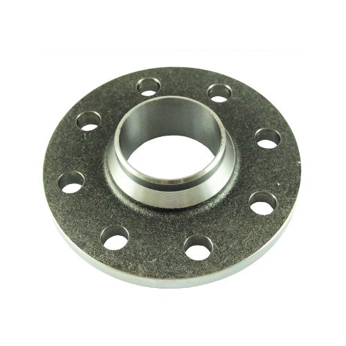
Weld neck (WN) → EN type 11
The tapered hub distributes the stresses, a single butt weld, bore = pipe inside diameter (flow-friendly). First choice for high pressure, high temperature and cyclic loading. EN equivalent: type 11 welding neck flange. Long weld neck (LWN) variant: extended hub, typically on vessels and heat exchangers (room for insulation).
Slip-on (SO) → EN type 01 plate flange
Pushed over the pipe and attached with two fillet welds (inside and outside). Cheaper and easier to align than a weld neck, but with lower strength and fatigue resistance – for moderate pressures and non-critical media. EN equivalent: type 01 plate flange (formerly DIN 2576). Note: do not confuse the plate flange with the flat face (facing form A) – the latter describes the sealing face, not the flange style.
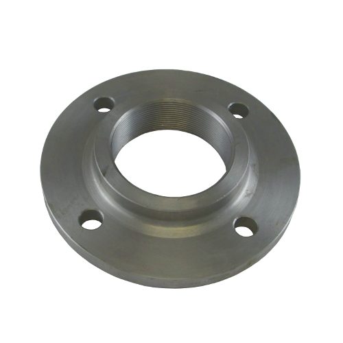
Threaded → EN type 13
The pipe is screwed in (NPT threads in the USA, BSP threads in Europe, i.e. Rp to EN 10226-1); no welding is required – making it an option wherever welding is to be avoided, for instance under project-specific constraints in hazardous areas. The permissible service limits follow from the applicable code, medium, pressure, temperature and project specification; common up to about 4″. Important: Rp threads (EN/ISO) and NPT threads (ASME) are different thread systems – similar nominal sizes alone do not make them interchangeable. EN equivalent: type 13 threaded flange.
Socket weld (SW)
The pipe is inserted into a socket and attached with an external fillet weld; before welding, the pipe is withdrawn about 1.6 mm from the socket bottom (expansion gap). That internal gap makes SW unsuitable for corrosive media (crevice corrosion). Rare in the EN world – there is practically no traded EN 1092-1 counterpart; the closest is type 12 (slip-on flange with hub), which is itself uncommon.
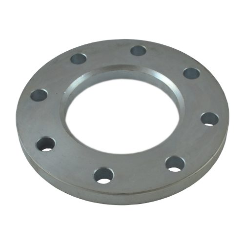
Lap joint (LJ) – loose flange with stub end → EN type 02 / type 04
The flange sits loosely behind a lapped pipe end and stays rotatable – which makes bolt-hole alignment easy. Economically attractive with expensive materials: only the wetted lapped end has to be stainless steel or a special alloy, while the loose flange can be carbon steel.
In the EN world the system of loose flange plus lapped end or collar takes the role of the lap joint – note that the type numbers identify two different groups of parts:
- Type 02 is the loose flange combined with the lapped pipe end type 33 (the EN counterpart of the stub end) or with the collars types 32/36/37.
- Type 04 is the loose flange for the welding neck collar type 34.
Always select and order loose flange and collar/lapped end as a pair. A rule of thumb from trading practice: with stainless steel the lapped end (type 33) is usually chosen, with carbon steel rather a collar – because in stainless the solid machined collar costs far more than the thin-walled lapped end.
Blind → EN type 05
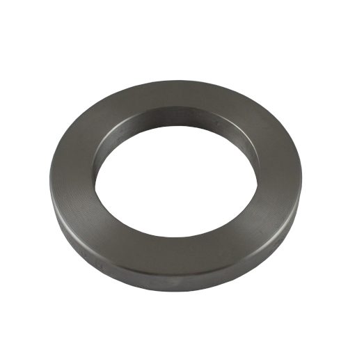
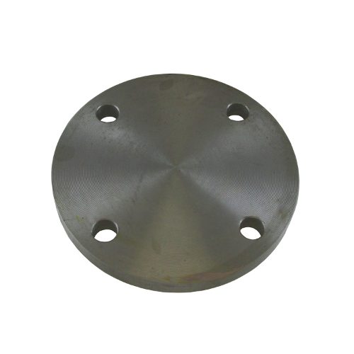
No centre hole – the disc has only the bolt holes, no passage – and closes pipe ends, vessel nozzles and spare branches. EN equivalent: type 05 blind flange.
Special styles (ASME environment)
Combination parts that unite flange and branch/fitting in one forging: nipoflange and weldoflange (flange + branch outlet, replacing tee + flange), elboflange (elbow + flange), latroflange (45° lateral branch + flange), swivel flange (rotatable ring for large-bore and offshore lines), expander/reducer flange (integrated size change of 1–2 steps – beyond that, install a reducer plus a standard flange). From metering practice: orifice flanges (ASME B16.36) and monoflanges (flange with integrated isolation/instrument function). These styles usually enter European plants through international specifications.
Weld neck or slip-on? (the most common selection question)
On narrow screens the table scrolls sideways.
| Criterion | Weld neck | Slip-on |
|---|---|---|
| Strength/fatigue | high (tapered hub, butt weld) | lower |
| Welding effort | 1 butt weld (with preparation) | 2 fillet welds (simpler) |
| Alignment | more demanding | easier |
| Component cost | higher | lower |
| Application | high pressure/temperature, critical media, cyclic load | moderate conditions, water/HVAC, non-critical |
Rule of thumb: the higher the pressure, temperature or number of load cycles, the stronger the case for a weld neck; the slip-on/plate flange is the economical answer for the non-critical standard case.
Facings beyond RF
Beyond raised face (RF) and ring joint (RTJ), the standards world (EN 1759-1/ASME) knows further facing pairings that are ordered by code in the trade: LM/LF (Large Male/Female), SM/SF (Small Male/Female), LT/LG (Large Tongue/Groove), ST/SG (Small Tongue/Groove) – i.e. male/female and tongue-and-groove systems in which two complementary flanges must always be combined. The principle is shown by the EN-1092-1 forms C/D (tongue/groove) and E/F (spigot/recess – in ASME terms male/female):
The fundamentals of the EN 1092-1 facing forms are covered in our flange guide; the comparison with the ASME facings (raised face, flat face, RTJ) is drawn in the standards comparison EN 1092-1 vs ASME B16.5.
Material quick reference (DIN ↔ ASTM)
Industry-typical equivalents for flange starting material:
On narrow screens the table scrolls sideways.
| ASTM | DIN/EN | Classification |
|---|---|---|
| A105 | P250GH/C22.8 | carbon steel |
| A350 LF2 | P355NL1 | low-temperature tough |
| A182 F304/F304L | 1.4301/1.4307 | stainless steel, austenitic |
| A182 F316/F316L | 1.4401/1.4404 | stainless steel, austenitic |
| A182 F316Ti | 1.4571 | stainless steel, titanium-stabilised |
| A182 F321 | 1.4541 | stainless steel, titanium-stabilised |
| A182 F12 | 13CrMo4-5 | creep-resistant |
| A182 F22 | 10CrMo9-10 | creep-resistant |
More on material designations and cross-references in our German-language materials section.
Frequently asked questions about international flange types
What is a type 11 flange?
Type 11 is the welding neck flange: butt-welded to the pipe, with a favourable force flow and better stress distribution – the choice for higher pressures, temperatures, load cycles and critical media. ASME counterpart: weld neck.
When is a welding neck flange the preferred solution?
For higher pressures, temperatures, load cycles, critical media, or wherever a favourable force flow and a high-quality welded joint are required; the hub reduces the stiffness step but calls for a matching pipe wall, weld preparation and qualified fabrication.
What is the difference between a weld neck and a slip-on flange?
The weld neck has a tapered hub that distributes stresses and is attached with a single butt weld – first choice for high pressure, high temperature and cyclic loading. The slip-on is pushed over the pipe and attached with two fillet welds: cheaper and easier to align, but with lower strength and fatigue resistance – for moderate pressures and non-critical media.
When is a socket weld flange suitable?
Mainly for smaller nominal sizes and higher pressure classes, provided the piping code and specification allow it. Watch the defined assembly gap at the pipe end, the weld execution and possible crevice corrosion – which is why it is not suitable for corrosive media.
Why are socket weld flanges unsuitable for corrosive media?
Before welding, the pipe is withdrawn about 1.6 mm from the socket bottom (expansion gap). This internal gap remains and promotes crevice corrosion – choose a different style for corrosive media.
When is a lap joint flange with stub end used?
In corrosion-resistant piping systems or where frequent dismantling is needed: the loose backing flange can be made of a cheaper material and can be rotated; the wetted stub end determines corrosion and facing suitability. Always select both parts as a pair.
What additional information does a loose flange require?
Besides standard, DN, PN and material of the loose flange itself, the matching collar, lapped end or welding neck collar must be specified unambiguously – material, sealing face, pipe connection size, collar outside diameter and the geometric compatibility of the pair.
May a slip-on flange be used as a loose flange?
Only if the standard design, collar outside diameter, bearing surface and project-specific approval allow it – fitting geometrically does not mean designed as a lap joint backing flange.
What should be considered with reducing flanges?
They join different nominal sizes but can create locally increased flow velocity, pressure loss and unfavourable stresses; clarify the design (concentric/eccentric), bore, gasket inside diameter and the permissible standard execution.
Find the right flange
You already know the style, DN and material? Zickwolff supplies weld neck, threaded, plate, blind and loose flanges to EN 1092-1 in carbon and stainless steel – from Germany, across Europe.
Send us your inquiryAll sectional and front-view drawings are schematic representations of the styles, not to scale – they make no statement about dimensional equality between EN and ASME designs. Technical basis: ASME B16.5, EN 1092-1, EN 1759-1, ASME B16.36; materials: ASTM A105/A350/A182 and their EN counterparts. All information without guarantee – the current standard texts and the manufacturers’ technical data sheets always prevail.