Installation guide · Flanges
Flange connections and installation: the system of flange, gasket and bolt
A flange connection is a demountable, pressure-tight connection between two components made using two flanges, a gasket and bolts with nuts. This page explains the flange connection as a system – what happens between two flanges: the sealing principle, the installation sequence with cross-pattern tightening, typical failure modes and inspection. The flange as a component (DN, PN, type numbers, sealing-face forms) is explained on the flange standards page.
- System
- Flange + gasket + bolt + installation
- Sealing principle
- Bolt preload force
- Tightening
- cross pattern, in stages
- Standards
- EN 1591-1 / EN 1591-4
What is a flange connection?
A flange connection is a demountable, pressure-tight connection between two components made using two flanges, a gasket and bolts with nuts. Tightness is not created by the flanges themselves but by the bolt preload force: it compresses the gasket between the sealing faces. Every flange connection is therefore a four-part system of flange, gasket, bolt and installation – if one component fails, the connection fails.
The components at a glance
Component
Flanges
Defined by the bolt-hole pattern (bolt circle (also called bolt circle diameter/BCD or pitch circle diameter/PCD), number of holes – typically a number divisible by four, evenly distributed), the sealing-face form and the design (welding neck, plate, loose, threaded, blind flange). Details: flange standards page.
Component
Gasket
Soft/fibre gaskets and PTFE for wide standard use (adaptable, limited surface pressure), spiral-wound gaskets for higher pressures and temperatures, metallic gaskets (e.g. ring-joint) for the highest demands. Selection depends on sealing-face geometry, medium, temperature and pressure. Used gaskets are never reused. Dimensions of the classic soft gasket: flat gasket to DIN 2690.
Component
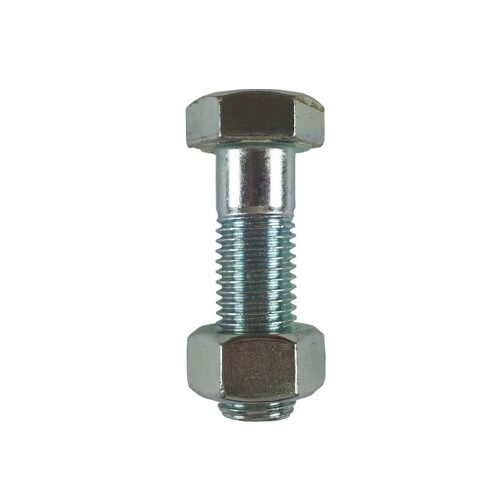
Bolts and nuts
Strength class, material and length must match the flange thickness, gasket and nominal pressure. With dissimilar material pairings (e.g. stainless-steel flange / steel bolt), watch for contact corrosion and different thermal expansion. Important: the hole diameter d1 in the dimension tables is not the bolt diameter – the bolt is always thinner than the hole (e.g. 18 mm hole → M16 bolt).
Influencing factor
Sealing-face surface
The roughness of the sealing faces is a decisive factor for the sealing effect – too smooth or too rough for the chosen gasket type leads to leaks (roughness values by sealing-face form: see flange standards page).
The fourth quantity of the system – proper installation – is not a component but a process; it is described in the “Installation sequence overview” section.
The sealing principle: preload is everything
Controlled tightening of the bolts creates the preload force that compresses the gasket. Both deviations are harmful: too little preload → leakage; too much preload → over-compressed gasket, over-stretched bolts, in extreme cases distorted flange plates. At elevated temperatures, cyclic pressures or additional pipework loads, the connection needs to be verified by calculation – the calculation method for this is provided by EN 1591-1 (bolt forces, gasket pressure, operating loads).
Installation sequence overview – our suggested approach
Overview, not an installation manual: the manufacturer's installation instructions and the plant's requirements govern; installing flange connections belongs in the hands of appropriately qualified personnel (cf. EN 1591-4).
- Clean the sealing faces and check for damage; choose a gasket to match the medium, temperature and sealing-face form.
- Set the bolts hand-tight, then tighten in a cross pattern in several stages (typical example: three stages at 30/60/100 % of the target torque) – this compresses the gasket evenly. The released installation instruction, the calculation and the manufacturer's data are binding.
- Check run-out/parallelism, followed by a final control pass using the torque or turn-of-nut method.
- Document: tightening values, lubricant, sequence, date.
Specific tightening torques depend on the gasket, bolt material and lubrication and come from the calculation or the manufacturer's data – so a torque table is deliberately omitted here.
Typical failure patterns
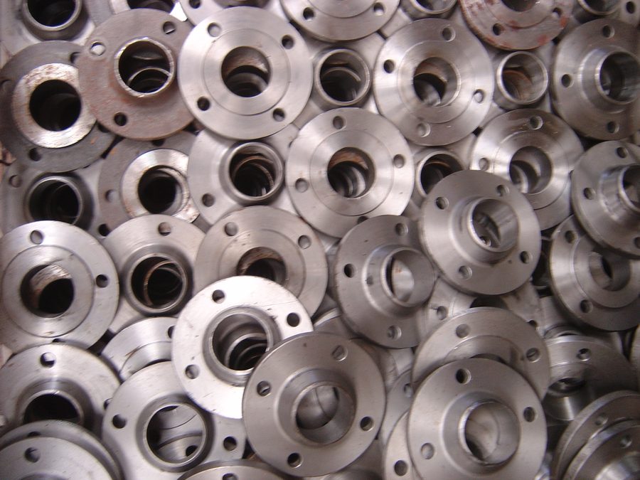
Under- or over-tightening, wrong gasket choice for the medium, damaged or contaminated sealing faces, gasket set/relaxation behaviour (missing retightening where specified), misalignment and resulting installation stresses, unsuitable bolt lengths, mixed/wrong lubricants, corrosion (crevice, contact corrosion). Most leaks are installation errors, not material defects – which is why EN 1591-4 specifically qualifies installation personnel for flange connections in pressure systems.
Inspection
Visual inspection (even gasket protrusion, bolt protrusion), leak testing hydrostatically or pneumatically depending on the code, supplemented e.g. by tracer-gas or acoustic methods.
Standards landscape (context)
- EN 1092-1: steel flanges (dimensions, types, sealing faces) – see flange standards
- EN 1591-1: calculation of flange connections
- EN 1591-4: qualification of installation personnel
- EN 13480: metallic industrial piping (overall code)
- ASME B16.5: the US counterpart for flanges
Frequently asked questions about flange installation
What checks are required before installation?
Compare flange marking against the specification, isolate the plant safely and depressurise it, clean the sealing faces and check for damage, verify parallelism and alignment, and check gasket, bolts, nuts, washers, lubricant and tools against the installation instruction.
What does ‘snug tight’ mean during pre-assembly?
An even, light contact state in which all components are seated and the flanges are parallel, without yet loading the gasket in an uncontrolled way. The specific value or tool belongs in the installation procedure – ‘hand-tight’ varies considerably between fitters.
Why are flange bolts tightened in a cross pattern?
Cross-pattern tightening in several stages compresses the gasket evenly and prevents the flanges from tilting. Three or more stages are usual; the number of stages and torque values are set by the released installation instruction, the calculation, or the manufacturer's data.
When is a cross pattern unsuitable?
With very high bolt counts, an alternative, validated pattern (e.g. to ASME PCC-1) can be more efficient and more even – but never as a spontaneous deviation without approval. The standard case remains cross-pattern tightening in several stages.
Why can a joint pass the pressure test and still leak later?
Operation brings higher temperatures, thinner gases, thermal cycling, vibration or chemical attack; heating changes bolt and gasket forces. A passed cold hydrotest therefore does not prove long-term tightness in process operation.
What are typical causes of a leak right after start-up?
Wrong or damaged gasket, unsuitable dimension, contaminated or scratched sealing face, misalignment, too little or too much preload, wrong lubricant, unsuitable bolts, or a missing walk-round inspection.
What is the first step when a flange leak is reported?
Secure the plant and personnel, establish the medium, pressure, temperature and hazard, and respond according to the operator's procedure – technical analysis only begins after the situation has been safely brought under control.
May a flange gasket be reused?
No. Damaged or already compressed gaskets are not ‘reshaped’ – they are discarded.
What does EN 1591-4 regulate?
EN 1591-4 regulates the qualification of installation personnel for flange connections in pressure systems – because most leaks are installation errors, not material defects.
Find matching flanges directly
You already know DN, PN and design? Zickwolff supplies flanges in carbon and stainless steel – gaskets, bolts and nuts included.
Send us your inquiryTechnical basis: EN 1092-1, EN 1591-1, EN 1591-4, EN 13480, ASME B16.5. All information without guarantee – the current standard texts and the manufacturers’ technical data sheets always prevail. Specific tightening values are provided by the connection calculation or the gasket manufacturer.