Push-fit systems · GF iFIT
Installing GF iFIT – step by step
An iFIT joint is made in five actions: cut to length, chamfer and calibrate, push the adapter on, push the module on, check. This page shows each step as GF specifies it – with the tool for it, the picture from the installation instructions and the fault that results if the step is skipped. Plus: how to undo a joint again, how the pipe is bent, and the videos from GF.
What you need
No power, no machine: the iFIT pipe shears (d16/d20) or the pipe cutter (d16–d32), the chamfering/calibrating tool for the dimension – and for every joint an adapter and a module. According to the manufacturer, pipe shears and chamfering/calibrating tool belong to every first order – we include them in the enquiry if you do not have them yet.
Installation in four pictures
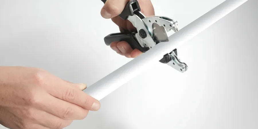
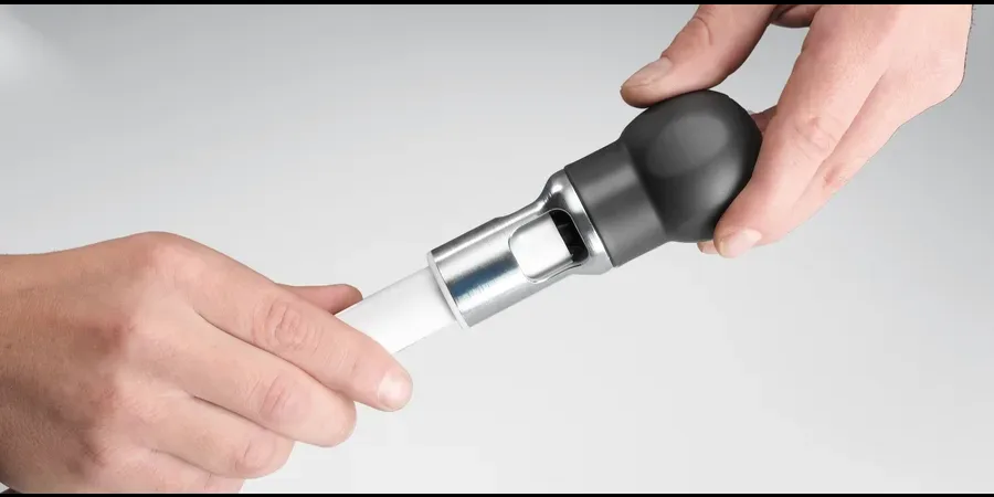
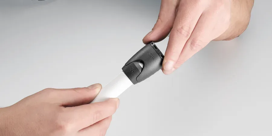
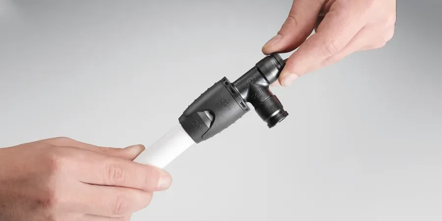
The nine steps
-
Cut the pipe square
Cut the pipe square (90°) with the iFIT pipe shears (d16/d20) or the pipe cutter (d25/d32) and look at the pipe end: cut straight, not oval. With conduit, cut the conduit back first.
Tools: iFIT pipe shears d16–d20 (762 101 108) or iFIT pipe cutter d16–d32 (762 101 117)
Typical fault: Pipe cut at an angle or oval: leak at the pipe (GF note).
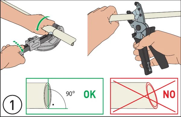
Pictogram from the GF installation instructions. Image: GF -
Chamfer and calibrate the pipe end – in one step
Place the iFIT chamfering tool of the dimension on the pipe end and turn it 1 to 2 revolutions: it chamfers the outside and calibrates the pipe round. The chamfer all round must be at least 1 mm (x ≥ 1.0 mm for 16 × 2, 20 × 2, 25 × 2.5 and 32 × 3) – remove chips, also inside. If the chamfer is too small, check the tool.
Tools: iFIT chamfering tool d16 (762 101 116), d20 (762 101 120), d25 (762 101 125), d32
Typical fault: Without a chamfer or with one too small, the O-rings are damaged on insertion – uncalibrated pipe is out of round – leak (GF note).
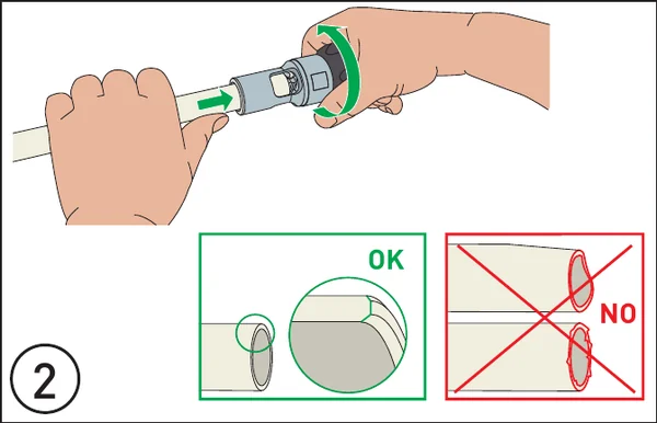
Pictogram from the GF installation instructions. Image: GF -
Push the adapter onto the pipe up to the stop
The iFIT adapter (individually packed, open only immediately before use – the sharp grip ring is inside, do not reach in) is pushed onto the prepared pipe end up to the stop. Check: the inspection window of the adapter must be completely filled by the pipe – that is the visible insertion depth.
Tools: no tool – adapter 16/20/25/32 (762 101 030/031/034/035)
Typical fault: Inspection window not completely filled: pipe not pushed in far enough – push further, otherwise no secure joint.
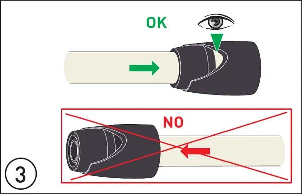
Pictogram from the GF installation instructions. Image: GF -
Push the module onto the adapter until it clicks
Push the module (elbow, tee, transition …) onto the adapter and press until it clicks audibly – the acoustic check. The module is now fixed to the pipe – two factory-fitted O-rings seal. There is no pressing. Modules with pipe contour: push an adapter of the same dimension onto the pipe contour, likewise up to the stop.
Tools: no tool
Typical fault: No click: module not engaged, no pull-out protection – do not push on at an angle, otherwise replace the adapter.
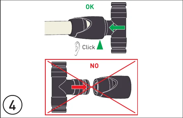
Pictogram from the GF installation instructions. Image: GF -
Pull-back test
Pull the pipe against the module: adapter and module may slide apart by up to 5 mm – that is the dynamic holding mechanism and, according to GF, not a defect – in operation and during the pressure test the pipe also moves back slightly. If the joint comes apart, the module was not engaged.
Tools: no tool
Typical fault: Joint slides more than 5 mm or comes apart: adapter not pushed on up to the stop or module without click.
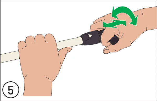
Pictogram from the GF installation instructions. Image: GF -
Leak test
Before closing wall or screed, fill the pipe, vent it and test it for leaks, record the result in the test report (test values as specified by the planner – we do not quote figures). That the pipe moves back a few millimetres during the pressure test is normal according to GF.
Tools: Test pump, pressure gauge
Typical fault: Without a test, a module that has not engaged goes undetected until the wall is closed.
-
Detaching and reusing – what GF says is possible
The joint can be detached, but the adapter is destroyed in the process and must not be reused (opened adapters: no warranty). Procedure according to GF: hold the collar of the half-shells with water-pump pliers, loosen the adapter housing anticlockwise with a second pair of pliers and unscrew it, pull the pipe off the support nipple, remove housing, support ring and grip ring, take the half-shells and support nipple out of the module, release the clamping ring with the pliers. The module is reusable – the pipe end is shortened by 6 mm (insertion depth of the grip ring), chamfered and calibrated again, then pushed on with a new adapter.
Tools: two water-pump pliers, new adapter
Typical fault: Reinstalling an opened adapter: no pull-out protection, no warranty.
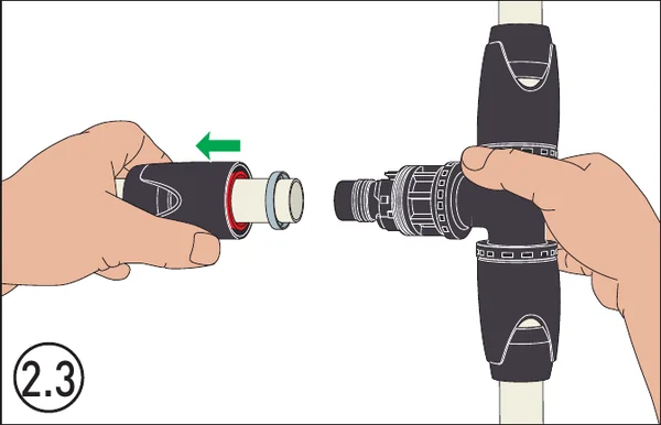
Pictogram from the GF installation instructions. Image: GF -
Routing and bending the pipe
iFIT pipes can be bent by hand: polybutylene pipe with a bending radius of 5 × d laid freely (16: 80 mm, 20: 100 mm, 25: 125 mm, 32: 160 mm) and 8 × d in conduit (16: 128 mm, 20: 160 mm, 25: 200 mm) – multilayer composite pipe by hand or with the external bending spring 5 × d (16: 80, 20: 100, 25: 125, 32: 160 mm), with the bending tool 3.5 × d (56/70/88/112 mm) – no internal bending spring, do not kink the pipe. Lay polybutylene pipe in conduit where it will no longer be accessible later – do not expose composite pipe permanently to daylight. We make no statements on fixing.
Tools: External pipe bending spring 762 101 112/113/114/115 (16/20/25/32)
Typical fault: Kinked pipe or radius below the minimum: pipe damaged (GF note).
-
Use system parts only
With iFIT use only pipes and adapters from the iFIT range – no third-party pipes, no components of other GF systems (INSTAFLEX, JRG Sanipex). Transitions to other systems go via the transition modules with thread or the transition to copper.
Tools: –
Typical fault: Third-party pipe in the adapter: grip ring and O-rings are not matched to it – leak, no system protection.
How to recognise a bad joint
Every push-fit joint can be checked from the outside – that is its strength. Five pictures that call for rework:
- Pipe cut at an angle or oval: cut again – a crooked cut does not seal.
- No chamfer or one too small: the O-rings are damaged on insertion – chamfer again, check the tool (chamfer at least 1 mm).
- Inspection window not completely filled: the pipe is not far enough into the adapter – push on up to the stop.
- No audible click: the module has not engaged and holds no pull – push on straight; if it was tilted, replace the adapter.
- Joint slides more than 5 mm under pull-back or comes apart: adapter not at the stop or module without click – rebuild the joint.
Up to 5 mm of slide under pull-back, on the other hand, is normal according to GF – that is the dynamic holding mechanism, not a defect.
The installation on video
GF shows the installation with hand tools and with a cordless tool, the installation on the pipe-contour module and the disassembly – the videos load only after a click. The chapter marks jump straight to the step. The English overview film comes first; the step films are in German.
Push-fit System iFIT – Simply faster to install · Video: GF Piping Systems (YouTube). The video loads only after your click – your browser then connects to YouTube (Google).
Leak test
Before wall or screed is closed, the pipe is filled, vented and tested for leaks – with test values as specified by the planner; the result belongs in the test report. That the pipe moves back a few millimetres in the process is normal according to GF.
Detaching and reusing – what GF says is possible
An iFIT joint can be detached – but the adapter is destroyed in the process and must not be reinstalled. The procedure according to GF: hold the collar of the half-shells with water-pump pliers, unscrew the adapter housing anticlockwise with a second pair of pliers, pull the pipe off. The module is reusable: shorten the pipe end by 6 mm, chamfer and calibrate again, push on with a new adapter. That distinguishes iFIT from every press joint, which can only be cut out – and makes corrections and later alterations easy.
Manufacturer documents
The GF documents are decisive for operating limits and installation. You can download them here – each entry states its edition.
- iFIT d16–d32 installation instructions from GF (PDF, 1.1 MB, as of 2025) – the manufacturer’s instructions in pictures, multilingual
Further reading
Parts and tools – what there is and what is in stock · Operating limits – media, temperature, installation · The five project guides · Parts-list tool.
Everything for the first installation
Tell us dimension and quantity – we put together modules, adapters, pipe and the tool set, from stock.
Send an inquiryYour inquiry to Zickwolff
Send us what you have – designation, standard, quantity, date. We will clarify the rest with you.
One item or a question
Send inquiry
Not in stock? We procure it – single items too.
Designation, standard and quantity are enough.
Several items
Send bill of materials
200 items? One parts list is enough – we deliver complete.
Attach it as a file.
Helpful if already known: project and country, date needed, certificates, packaging and language of the packing lists. If anything is missing, we will ask.
It is urgent
Request express
When do you need it? Express delivery, to the site if required.
Tell us by when you need the material – we will tell you what is possible.
Technical basis: GF practice guide for installation and repair instructions (08/2026, pp. 13–17, 91–92), GF iFIT installation instructions 762 100 469 (09/2020), GF iFIT product range (07/2025) – authorised-dealer material, use approved; pictures: GF. Test values of the leak test as specified by the planner. Information without guarantee – the binding approval remains with the manufacturer.